

Vr sensor polarity
-
Number-One
- contributor

- Posts: 101
- Joined: Sun Jan 05, 2014 2:59 pm
Vr sensor polarity
Hi, how can i know vr sensor polarity? I know if i connect it to a scope "in positive mode" i have one wave, if i change the wires i have another wave (like a mirror). How to know which pin is the right one to conect it to crk2+ without using a scope?

Re: Vr sensor polarity
I seem to recall if you get it wrong, there is a bit in software that can flip what the digital signal means. Other than the, I'd say you would need to spin it such that a skipped tooth passes, then see if the digital signal is high or low. If it's wrong, flip the VR wires.
Welcome to the friendlier side of internet crazy 
-
Number-One
- contributor
- Posts: 101
- Joined: Sun Jan 05, 2014 2:59 pm
Re: Vr sensor polarity
Yes, but how can i know if the signal is positive or negative? I can´t see it without scope.
Re: Vr sensor polarity
As a semi educated guess, you might be able to connect a multimeter (analog needle style would be better) to the sensor, noting which sensor wire connected to + and which wire is -. Then take some piece of metal or perhaps a magnet and move it rapidly in front of the VR sensor. If you see a + voltage, your + is connected to + side. If you see a - swing, then the + is connected to the - side. I would expect the signal to be very short lived, so a digital meter might simply smooth it out and you might not get any reading. If you get a reading, I would expect it would be very small, so you are probably best off setting your meter to the minimum scale, which will show the most variation from your sensor.
Also you may find interesting results if you measure the resistance, then put the sensor near metal. You may be able to see a change in resistance which may allow for a slower meter to register a reading. This would again be better noticed on a low scale. If you get a reading from this, I can make a suggestion on if the + or - lead was connected to the + terminal of the meter.
Hmmm, you could also use a LED. If I only had a VR sensor, I could do some tests and let you know what works.
Welcome to the friendlier side of internet crazy
-
AndreyB

- Site Admin
- Posts: 14333
- Joined: Wed Aug 28, 2013 1:28 am
- Location: Jersey City
- Github Username: rusefillc
- Slack: Andrey B

Re: Vr sensor polarity
Let's begin from the beginning. Why do we need to know the polarity?
Very limited telepathic abilities - please post logs & tunes where appropriate - http://rusefi.com/s/questions
Always looking for C/C++/Java/PHP developers! Please help us see https://rusefi.com/s/howtocontribute
Always looking for C/C++/Java/PHP developers! Please help us see https://rusefi.com/s/howtocontribute
-
abecedarian

- Posts: 386
- Joined: Fri Nov 15, 2013 10:49 am
Re: Vr sensor polarity
IIRC, the MAX9924/5/6/7 trigger on the positive going negative transition. So, if your polarity is reversed, your signals are delayed by 1/2 tooth, which in the case of a 60-1 is 3 degrees, a 36-1 is 5 degrees, and 12-1 would be 15 degrees.
Even considering single-ended VR, the same would be true, i.e. the chip would trigger on the falling edge of the input after hysteresis has been accounted for.
Even considering single-ended VR, the same would be true, i.e. the chip would trigger on the falling edge of the input after hysteresis has been accounted for.
You can lead the horticulture but you can't make them think.
Re: Vr sensor polarity
I fail to see why polarity is all that important of a concern. I understand it is important if you don't have control over whether the software triggers on raising or failing edge. However rusEFI has that ability. If the polarity is flipped, all that happens is the software will need to trigger on the raising edge instead of the falling edge. I understand that especially with OEM ECU's you have to trigger on the raised to falling edge, which has caused several people to claim there is a "correct" or "wrong" wiring. Except Honda, which apparently uses the opposite polarity, and is often claimed to have done it "wrong".
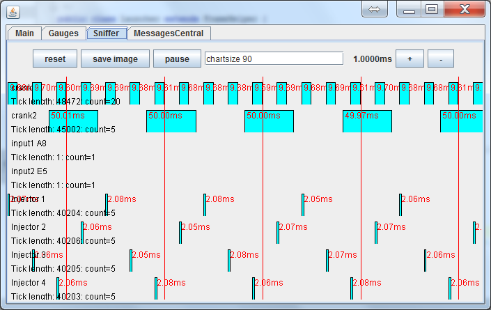
In rusEFI, you connect the wires, then crank it over. In the dev console you can see the captured wave form. If you have a skipped tooth wheel and if the polarity is flipped, you'll see the skipped tooth as a 1 instead of a 0. At that point you can either flip the polarity in software or physically, such that the dev console indicates the skipped tooth is a 0 instead of a 1. Snap shot of dev console below. I couldn't find a picture of a skipped tooth, but this shows a wheel that was properly decoded.
In rusEFI, you connect the wires, then crank it over. In the dev console you can see the captured wave form. If you have a skipped tooth wheel and if the polarity is flipped, you'll see the skipped tooth as a 1 instead of a 0. At that point you can either flip the polarity in software or physically, such that the dev console indicates the skipped tooth is a 0 instead of a 1. Snap shot of dev console below. I couldn't find a picture of a skipped tooth, but this shows a wheel that was properly decoded.
Welcome to the friendlier side of internet crazy

Re: Vr sensor polarity

This is oscilloscope of VR sensor. the true position detected when signal is raised through zero - in this condition a center of teeth is on the center of VR sensor.
You can connect the LED to the output circuit of detector and bring it to the rotating ring. You should see something similar to this:

If the ring is rotated counterclockwise, you should see the same picture, just like me
Теория хороша в том и только том случае, если она может достоверно предсказать результаты каждого нового опыта
-
Number-One
- contributor
- Posts: 101
- Joined: Sun Jan 05, 2014 2:59 pm
Re: Vr sensor polarity
kb1gtt wrote:I fail to see why polarity is all that important of a concern. I understand it is important if you don't have control over whether the software triggers on raising or failing edge. However rusEFI has that ability. If the polarity is flipped, all that happens is the software will need to trigger on the raising edge instead of the falling edge. I understand that especially with OEM ECU's you have to trigger on the raised to falling edge, which has caused several people to claim there is a "correct" or "wrong" wiring. Except Honda, which apparently uses the opposite polarity, and is often claimed to have done it "wrong".
In rusEFI, you connect the wires, then crank it over. In the dev console you can see the captured wave form. If you have a skipped tooth wheel and if the polarity is flipped, you'll see the skipped tooth as a 1 instead of a 0. At that point you can either flip the polarity in software or physically, such that the dev console indicates the skipped tooth is a 0 instead of a 1. Snap shot of dev console below. I couldn't find a picture of a skipped tooth, but this shows a wheel that was properly decoded.
Ok, thank you for the explanation. i'm glad to read this.
Re: Vr sensor polarity
Here are some links I stumbled upon in my learning of VR polarity stuff.
This PDF notes some way to test the polarity. http://www.linkecu.com/support/documentation/technical-notes/variable-reluctance-sensors-tech-note.pdf
Megamanual notes it will change the raising edge from trailing edge and claims that you can flip the polarity in software. http://www.megamanual.com/ms2/pickups.htm
Same here they noted you can simply flip the polarity in software. http://www.import-car.com/ignition-sensor-diagnostics-variable-reluctor-hall-effect-and-magneto-resistive-sensors/
Welcome to the friendlier side of internet crazy
-
AndreyB
- Site Admin
- Posts: 14333
- Joined: Wed Aug 28, 2013 1:28 am
- Location: Jersey City
- Github Username: rusefillc
- Slack: Andrey B
Re: Vr sensor polarity
That batch of boards has created a spike in support requests of all kinds, this really shows how much we are lacking on the documentation side 
One of the open questions: how can we test the MAX9926 chip in VR configuration on a bench without a real VR?
For example, can I put a AAA battery to the sensor one way and then apply same battery with reverse polarity - would I get the trigger even this way? Is it safe to test MAX9926 with 1.5v battery? What about three AA batteries (that's because I have an enclosure with wires)
Very limited telepathic abilities - please post logs & tunes where appropriate - http://rusefi.com/s/questions
Always looking for C/C++/Java/PHP developers! Please help us see https://rusefi.com/s/howtocontribute
Always looking for C/C++/Java/PHP developers! Please help us see https://rusefi.com/s/howtocontribute
Re: Vr sensor polarity
how about any smartphone + pure sine wave generator + minijack?
Re: Vr sensor polarity
Yup, all those options should be fine.
Welcome to the friendlier side of internet crazy
-
AndreyB
- Site Admin
- Posts: 14333
- Joined: Wed Aug 28, 2013 1:28 am
- Location: Jersey City
- Github Username: rusefillc
- Slack: Andrey B
Re: Vr sensor polarity
Cool, it does work with a battery - http://rusefi.com/wiki/index.php?title=Manual:Hardware_Trigger#Bench_testing_VR_configuration
Very limited telepathic abilities - please post logs & tunes where appropriate - http://rusefi.com/s/questions
Always looking for C/C++/Java/PHP developers! Please help us see https://rusefi.com/s/howtocontribute
Always looking for C/C++/Java/PHP developers! Please help us see https://rusefi.com/s/howtocontribute
-
abecedarian
- Posts: 386
- Joined: Fri Nov 15, 2013 10:49 am
Re: Vr sensor polarity
Will it work with voltages from 4mV to 400V... and with single-ended VR?
*edit- Yeah, I sort of pulled those numbers from my arse... but I think it's generally a reasonable question which flipping a battery around can't answer.
*edit- Yeah, I sort of pulled those numbers from my arse... but I think it's generally a reasonable question which flipping a battery around can't answer.
You can lead the horticulture but you can't make them think.
Re: Vr sensor polarity
hence a proper setup is advisable - use a real vr sensor you are gonna install on your vehicle, use the toothed wheel you are gonna install on your vehicle, and make this wheel spin at the RPM you are expecting your engine will work… 
Re: Vr sensor polarity
Agreed, we really need to measure a setup with a real VR and make some measurements.
I understand reasonably realistic real world voltage levels are from 4mV to 50V. Once upon a time, in a forum far far away, the forum administrator once claimed (then removed the post) that with a hot VR you could get 300V. I'm a skeptic about 300V, but I'm also ignorant, so I designed Frankenso and Frankenstein to handle above 150V. To get above 150V you'll need conformal coat or add potting to get the creepage to levels that are lower than IEC 60950 suggestions. Also to get 150V, you have to keep it in a reasonably low humidity low dust environment. I know I'm probably being a bit conservative by using the published creepage as the design guide. I would bet in the real world you'd be just fine with 300V and cabin mounting. However until I get some real world data, I'm using the published specs as the design guide and suggested practice. So it should be able to do 4mV and 300V, but it has not been tested to those limits as of yet.
I understand reasonably realistic real world voltage levels are from 4mV to 50V. Once upon a time, in a forum far far away, the forum administrator once claimed (then removed the post) that with a hot VR you could get 300V. I'm a skeptic about 300V, but I'm also ignorant, so I designed Frankenso and Frankenstein to handle above 150V. To get above 150V you'll need conformal coat or add potting to get the creepage to levels that are lower than IEC 60950 suggestions. Also to get 150V, you have to keep it in a reasonably low humidity low dust environment. I know I'm probably being a bit conservative by using the published creepage as the design guide. I would bet in the real world you'd be just fine with 300V and cabin mounting. However until I get some real world data, I'm using the published specs as the design guide and suggested practice. So it should be able to do 4mV and 300V, but it has not been tested to those limits as of yet.
Welcome to the friendlier side of internet crazy
-
abecedarian
- Posts: 386
- Joined: Fri Nov 15, 2013 10:49 am
Re: Vr sensor polarity
The crank VR's on my motorcycle can generate over 380v peak to peak.
In retrospect, I should probably think myself lucky since my install will have 6 VR sensors to choose from....
2 based on camshaft: one for each cylinder reflecting TDC compression (each generates ~14v peak)
2 based on crankshaft: one for each cylinder reflecting TDC position (each generates ~380v peak)
2 based on crankshaft: one for each cylinder sensing teeth on a 32 tooth trigger wheel (these are added on / not stock so don't know peak but I expect ~180-200v)
In practice, the first 2 on the camshaft only affect when the injectors fire so +/- a few degrees crank rotation won't upset much.
The second 2 on the crankshaft are used to determine when spark happens so if they're not phased correctly, that can be an error of up to 5 degrees- not something a 17PSI boosted turbo engine would tolerate for very long.
The last 2 are add-ons because the none of the others will give me accurate crank position on their own, and 32 teeth is all I can fit in the area.
You can lead the horticulture but you can't make them think.
Re: Vr sensor polarity
Do you have an extra VR sensor, crank wheel, and ability to spin the crank wheel? AKA how do we run a physical test?
Welcome to the friendlier side of internet crazy
-
abecedarian
- Posts: 386
- Joined: Fri Nov 15, 2013 10:49 am
Re: Vr sensor polarity
Matter of fact.... (this should look familiar to some)kb1gtt wrote:Do you have an extra VR sensor, crank wheel, and ability to spin the crank wheel? AKA how do we run a physical test?
- cxtrigger (3).jpg (40.5 KiB) Viewed 22450 times
*edit- Forgot to mention I can get 0.4-0.8v from the sensors just passing a precision screw driver across the face of them.
You can lead the horticulture but you can't make them think.
Re: Vr sensor polarity
I seem to recall my Dremel goes to around 4k to 5kRPM, and it has an adjustable speed switch. You can adjust anywhere from reasonably low RPM to full RPM with an analog slider. Do you have a Dremel? Should I find mine and send it to you for testing purposes? Would you be willing to let me borrow parts if I find the Dremel? Are there reasonably low cost parts that I can obtain to do the same test here? How do we do a test with a Dremel or equiv high speed RPM tool?
Welcome to the friendlier side of internet crazy
-
AndreyB
- Site Admin
- Posts: 14333
- Joined: Wed Aug 28, 2013 1:28 am
- Location: Jersey City
- Github Username: rusefillc
- Slack: Andrey B
Re: Vr sensor polarity
At some point I did the same test, the same results with non-precise pliers. A piece of metal definitely allows for a full VR sensor + MAX chip + rusEfi firmware integration test.abecedarian wrote:Forgot to mention I can get 0.4-0.8v from the sensors just passing a precision screw driver across the face of them.
Very limited telepathic abilities - please post logs & tunes where appropriate - http://rusefi.com/s/questions
Always looking for C/C++/Java/PHP developers! Please help us see https://rusefi.com/s/howtocontribute
Always looking for C/C++/Java/PHP developers! Please help us see https://rusefi.com/s/howtocontribute
-
abecedarian
- Posts: 386
- Joined: Fri Nov 15, 2013 10:49 am
Re: Vr sensor polarity
@kb1gtt- the parts I have came from 82 Honda GL500. The VR pickups are stock and the centrifugal advance mechanism was modified to carry the gear/trigger which was purchased separately and required boring the gear and press-fitting it on the shaft with a few tack welds for good measure. I estimate I have about $75 tied up in it. I do have a Dremel and I believe its top speed is 30K RPM but the weight of the gear assembly may be a bit much for it. Also would need to figure out how to drive it since the arbor on the Dremel are quite small.
As for what to test with it, I'd say an oscilloscope to get peak voltage measurements and frequency count should suffice, but unfortunately I do not have that equipment.
As for what to test with it, I'd say an oscilloscope to get peak voltage measurements and frequency count should suffice, but unfortunately I do not have that equipment.
You can lead the horticulture but you can't make them think.