I spent more time thinking about the soft startup circuit. A 1 Ohm power resistor on the power connection would do everything I want except maybe cause a 1V drop during engine cranking. You could use a mosfet to bypass the power resistor after the system powers up, but then you could use a mosfet to do the entire soft start... f your power cap is large enough to ride thru the initial voltage drop due to cranking ( 50 mSec.? ), you could skip the mosfet.
On the compiler subject, I guess there will be some education coming my way. I dont see VLE being a big deal, I would expect you could compile something either way, if it fits in memory you should be OK. VLE would save memory space and also speed up the processor because effectively you have more memory bandwidth so far as reading instructions go.
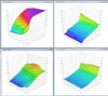
I've been looking at the VR inputs some more, because I want to understand the issues about the input filter. I put a timing wheel in my drill press and started looking at low RPM signals with a VR sensor. I'll buy a stock Ford sensor for a 302 next week. Here's a pair of traces, one with a 10k resistor for a load and the other with a 100 Ohm resistor for the load. These pictures are around 550 RPM.
I am surprised the voltage didn't drop further with a 100x increase in load, it dropped from about 2V to about 200mV. Next will be to add a couple of diodes etc. and see what it looks like.
Attachments
VR_10k_550RPM.jpg (394.19 KiB) Viewed 19844 times
VR_100_550RPM.jpg (421.16 KiB) Viewed 19844 times
Last edited by Horizenjob on Sat Mar 26, 2016 10:59 pm, edited 1 time in total.
I'm confused, I can't seem to get the pictures to work. TIFF's are a propitiatory format, which makes them less portable. I would suggest a PNG for cartoon graphics and a JPG for picture graphics. If you don't have PNG for some reason, you can use GIF's instead, but keep in mind GIF's had security issues once upon a time, so some times those have issues being viewed as well.
Fixed the picture for you, I meant to upload a jpg but usually I especially intend to do that after the forum refuses to load the tiff. THis forum did allow it though so my normal thought process was interrupted!
I would expect that as long as you aren't saturating the core, the sensor picks up a fairly constant watts. Then your voltage would be P=(V^2)/R --> (P*R)^0.5=V.
So (2V^2)/10k = 0.4mW, then (0.2V^2)/100 = 0.4mW. So it seems the voltage level is as I would expect. If you want to predict the voltage, you could use (0.4mW*R)^0.5 = V. As well you could see how many mW's you get at high RPM.
If you see that mW change, it would indicate you have saturated the core and are loosing energy. I see a slight skewing of the signal based on these different load resistors. One is a bit more pointy, the other is more sine wave.
Hi Jarrod, thanks. Meant to answer earlier. I think I either did the math in my head or also used a different trace, anyway you did it right.
Finally got to run the VR sensor with a diode clamp. I'm much happier. We'll see if the Maxim chips are happy too.
This is with a pair of scrap diodes I had lying around. I'm thinking on the board I might use a BAV99 ( from memory here ). It's a pair of diodes in series so the voltage peaks would be twice as high as these pictures. You can buy it with 2 of these pairs in an SO8 package, so it looks easy to use.
These are cheap parts and have about 100x as much current capacity as the internal diodes on the MAXIM chip. Doing this clamp on the outside of the chip means you don't have to dump a bunch of current into a little chip trying to measure your signal for you. I notice that the spec sheet says the jitter and delay is much worse when the input is saturated. dCan't imagine a 100 nSec difference would matter much to an engine, but I should do he math I guess.
The jitter can be an issue, we had issues with the 5634 being sensitive to jitter. Even tough we had maxed out the windows and such, it wouldn't sync reliably this lower level jitter can be more of an issue than your intuitions might have you think. However that was really an issue with the decoder software.
Sorry I upload the wrong file, I converted it then clicked on the wrong one. Funny the forum software let me delete the file but not reload it.
Here is what the trace looks like. More or less what you would expect. I'll try a faster RPM on the drill press tomorrow. I was a little surprised how low the voltage was, but there is not much current at this speed. These diodes are cheap and have very fast recovery so I hope they will work well.
You need to limit the negative swing of the VR to within -0.3V of ground or you will be outside of the working range of the Maxim chip, then you risk pushing the rails up and down which can shift the reference voltage and cause jitter - unless you are using the internal 2.5V offset.
The signal swing is what I was working on. The above trace shows the signal with a pair of diodes for voltage clamps. It seems better to do the clamp off the chip for the reasons you mention, it just doesn't make sense to dump current into a little chip.
These diodes gave a .9V signal swing and that is at 550 RPM. I was thinking of using a pair of diodes in series to give more voltage swing, but this may be enough.
You must do the clamping off-chip, the datasheet is quite clear that you should not put a negative voltage (<-0.3V) into the input of the differential amplifier; the behaviour of the output is not specified for voltages outside the common mode range. A diode clamp to rail isn't going to be adequate because the voltage drop across it is too high.
I should be more clear. The diodes I am using to clamp are between the signal lines, they limit the differential voltage to a diode drop, it will never exceed something like 1.2V and maybe not reach even that.
Horizenjob wrote:I should be more clear. The diodes I am using to clamp are between the signal lines, they limit the differential voltage to a diode drop, it will never exceed something like 1.2V and maybe not reach even that.
Ah, I understand now, however that stills leaves the common mode issue, how are you off-setting the input voltage?
I'm using the Maxim 9926, so am expecting the chip to reference the common mode voltage. It appears to have an internal 100K resister setting the positive leg to the internal bias voltage.
It doesn't seem like a very strong connection to the bias voltage though. Do you think I should use external parts to generate the bias voltage and use that thru a smaller resistor to set the common mode voltage?
Horizenjob wrote:I'm using the Maxim 9926, so am expecting the chip to reference the common mode voltage. It appears to have an internal 100K resister setting the positive leg to the internal bias voltage.
It doesn't seem like a very strong connection to the bias voltage though. Do you think I should use external parts to generate the bias voltage and use that thru a smaller resistor to set the common mode voltage?
The datasheet states the Maximum input range for the pin is -0.3V - VCC+0.3V so the internal diodes are clearly for short term protection only, I would expect that any current flowing through them is likely to cause jitter. The operating range is given as:
INPUT OPERATIONAL AMPLIFIER (MAX9925/MAX9927) Input Voltage Range IN+, IN- Guaranteed by CMRR 0 to VCC +0.3V
I haven't read the datasheet fully so that may be at the pin or at the differential amplifier itself. I have an evaluation board here somewhere, from memory it has a jumper to apply an external bias voltage; it would be worth looking for the datasheet for the dev board.
Not to knock anyone here, but I think a good, hard look at the datasheet for the MAX992x chips as well as a deep study of the evaluations kits might be in order.
You can lead the horticulture but you can't make them think.
Not to knock anyone here, but I think a good, hard look at the datasheet for the MAX992x chips as well as a deep study of the evaluation kits
I really have read the datasheet. Honest. Several times even. There is not much info in the evaluation kit information, so not so sure how deep it can be studied.
Abecedarian, is there something specific you're trying to say?
Maxim expects to do the clamping on chip, I'd rather take it off... If it doesn't work it's not like there isn't a fallback position. I'd just like to build a rugged ECU and if it costs $1 more to ruggedize a VR channel that's not bad.
I see the eval kit uses the 4X 5kohm resistors, very similar to what I did. I did this to get a higher working voltage. I see they used 1206 instead of 0805 though. That might be of interest. I used 0805 as they are pretty close to a 100% survival rate when thermally cycled. While 1206 and larger have about a 50% survival rate. The 1206 depends on what it's made from, if it's made from something with a thermal expansion rate that's similar to FR4, then it survives, if not then it fails. Seeing this board, I'm tempted to consider 3X of 3.33kohm 0805's. I would likely suggest a new design consider the same.
The datasheet doesn't say much about how much current is acceptable to flow through the clamping diodes. The 10kohms at 300V would conduct about 30mA, which is about 9W of energy to be dissipated and about 0.03W of that is dissipated by the MAX diodes. You would need a really hot VR at really fast RPM to generate 9W of energy, and even if you did have such a hot VR, not much of the energy is dissipated by the MAX chip. Most applications will only see about 50V, and the above test VR was generating 0.4mW at lower RPM. I think the big concern is if you have more than a 30mA load on the +V rail pulling it down. If you don't you run a potential over voltage risk. Horizenjob is attempting to avoid that issue by using clamping diodes in paralleled with chips inputs that clamp before hitting the 5V rails. This prevents that energy from being dumped to the + and gnd rails.
At the very top of the datasheet Maxim claims 40 mA max for IN1+, IN1-, IN2+, IN2-.
It's nice the Maxim part is auto qualified. They don't mention ESD in the datasheet though. The TVS I am using on ECU inputs are 0603 SURGX and cost about $0.09. OEMs avoid this cost, but I don't think it's a high cost for an aftermarket unit especially considering that it's inputs may be handled a lot more than a car that works for 200,000 miles after it is sold.
Those TVS don't want to see the high voltages possible from the VR though, so clamping would be nice. It also removes concerns about the input resistors and the wiring.
It is also worth some effort to reduce parts count. I'm only using 0603 10K resistors at the moment. The ones I am getting are pulse and ESD capable and rated 1/4W. The resistors in the eval kit are quite large, but not ESD rated. I don't have the experience to really know where to draw the lines here.