

I seem to recall that 12 psig is around the high end of what the carb fuel pumps provided. So it wouldn't surprise me if an early injector system used that same pressure.
About the max 9926 chip, I see what you are saying. In the below on page 3 it notes the "Watchdog Timeout for Adaptive" is typically 85mS but could be as much as 125mS or as little as 45mS. In the picture you posted, I'm assuming that's your single tooth wheel, running at 480RPM, which is pulsing about 125mS. Pulses which happens that slow will cause the adaptive window to reset, and it will reset to 33% from the peak to peak voltage in that window, with a minimum around 5 to 10 mV. This is causing a small amount of noise to cause a false trigger. If you were to rotate the engine faster, it would catch a pulse in the window and you'd be all set. As well I expect the 4 tooth wheel would be pulsing once every 31.25mS, so the 4 tooth wheel would be OK, but the CAM is causing some noise issues as lower cranking RPMs.
http://datasheets.maximintegrated.com/en/ds/MAX9924-MAX9927.pdf
I expect you'll have that same issue with the polarity flipped or not. It looks like you are using your scope with GND strap to measure a differential signal, as well I don't expect a 2.5Vp-p signal for such a low RPM. I fear your VR may be a hot one, or your scope might be reading incorrectly. Perhaps the 10X vs 1X scale was not correct. I see it was on the 10X setting for channel 2. Can I get a verification the channel 1 was really measuring 2.5Vp-p? If it is, can you crank you drill up to your max RPM and see what kind of voltages you get then? You may need to install a loading resistor. I expect you currently do not have R111 or R112 installed. You may need that if your VR is supper hot. Also did you use the 5k's noted for R102, 107, etc? Where are you measuring your VR signal, I'm assuming you're measuring the VR directly. If so remember the max9926 will be seeing that signal after the resistors, so the max chip is likely seeing a much lower voltage than what is on the screen. As well you were probably only looking at one side of the VR, not the differential signal that the max chip is seeing.
Also about that 2.5V DC offset, this tells me you have the GND strap connected to the MCU negative or chassis GND. Be careful doing this, as your scope GND strap is connected to your wall outlet GND wire. You can easily get GND loop issues that often cause problems. You'll likely be best off taking that measurement with ch1 on one side and ch2 on the other side with the GND straps connected together. This makes your scope a differential sensor instead of single ended, and prevents GND loop issues. Then if you connect ch1 to one side of R111 an ch2 to the other side of R111 to ch2, then you'll see what the max chip is seeing. But beware do not connect your GND wire to either side of the max chip directly, it will short your 2.5V bias to GND which may break something.
Russian, how hard is it to make the CAM signal less sensitive, such that it only cares about a CAM pulse +/- 45 degrees from the 4 tooth wheel? If that can be done in software, it would allow him to accurately detect the low RPM cranking situations. If not then it will likely be a much harder item to resolve in hardware. Is there any chance the CAM is already less sensitive like that? Would this extra pulse on the CAM at low RPM cause a problem with the wheel decoder?
1970 Datsun pickup L16 TBI conversion
-
kb1gtt

- contributor

- Posts: 3779
- Joined: Tue Sep 10, 2013 1:42 am
- Location: ME of USA

Re: 1970 Datsun pickup L16 TBI conversion
Welcome to the friendlier side of internet crazy 
-
mattf
- Posts: 15
- Joined: Fri Oct 16, 2015 7:31 pm
Re: 1970 Datsun pickup L16 TBI conversion
good points,
I agree the amplitude of the VR signal looks high for that RPM. I did not populate R111,112, and R102-110 are all 5k each. What is the max signal allowable by the max 9926? I was measuring with the probe ground lead connected to the uC ground, and the probe connected directly to the VR sensor. Directly connecting the scope probe to the positive input side of R111 would give a more accurate result since it would show the effect of the input low pass filter.
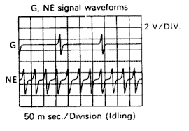
After a quick google search (the image above is from the original application of my sensor setup), it looks like most VR sensor signals show the signal ramping positive before flipping negative (opposite to what I have been proposing). This suggests I have been wrong, and that this is an issue with my system, and I need to fix my setup. I think I can do a couple things to reduce the amplitude of the signal between pulses so it stays below the default threshold level:
1) add R111 and R112 to reduce the amplitude of the signal. I think this is the real solution. Since the signal response is so large, I can reduce it significantly and keep it below the threshold, without compromising the ability of the circuit to detect the tooth at low RPM.
2) I can increase the gap between the sensor and the tooth.... on second thought I don't think this is a good idea. It will decrease the signal peak amplitude, but won't decrease the between-tooth signal amplitude, which is what is currently causing the problem.
-Matt
I arrived at the same conclusion regarding the source of the false triggers, however I wasn't able to reproduce the false triggers with the polarity flipped. My conclusion was that it was because the MAX9926 is detecting the signal going above a positive threshold. With the polarity flipped the signal ramps negative before flipping positive, so no false triggers are produced.kb1gtt wrote: About the max 9926 chip, I see what you are saying. In the below on page 3 it notes the "Watchdog Timeout for Adaptive" is typically 85mS but could be as much as 125mS or as little as 45mS. In the picture you posted, I'm assuming that's your single tooth wheel, running at 480RPM, which is pulsing about 125mS. Pulses which happens that slow will cause the adaptive window to reset, and it will reset to 33% from the peak to peak voltage in that window, with a minimum around 5 to 10 mV. This is causing a small amount of noise to cause a false trigger. If you were to rotate the engine faster, it would catch a pulse in the window and you'd be all set. As well I expect the 4 tooth wheel would be pulsing once every 31.25mS, so the 4 tooth wheel would be OK, but the CAM is causing some noise issues as lower cranking RPMs.
http://datasheets.maximintegrated.com/en/ds/MAX9924-MAX9927.pdf
I expect you'll have that same issue with the polarity flipped or not.
Good point regarding ground loops from the scope probe ground leads. In this case the rusEFI was floating (USB powered from my laptop which doesn't have a ground lead on it's power adapter). I think the scope scales are correct, based on the 2.5V bias from grounding the probe to uC ground. You are correct I am not producing a proper differential measurement of the VR sensor, however it seems that the MAX9926 holds the -ve VR signal at the bias voltage (2.5V), so the signal shown is correct with the exception of the 2.5V offset.kb1gtt wrote:It looks like you are using your scope with GND strap to measure a differential signal, as well I don't expect a 2.5Vp-p signal for such a low RPM. I fear your VR may be a hot one, or your scope might be reading incorrectly. Perhaps the 10X vs 1X scale was not correct. I see it was on the 10X setting for channel 2. Can I get a verification the channel 1 was really measuring 2.5Vp-p? If it is, can you crank you drill up to your max RPM and see what kind of voltages you get then? You may need to install a loading resistor. I expect you currently do not have R111 or R112 installed. You may need that if your VR is supper hot. Also did you use the 5k's noted for R102, 107, etc? Where are you measuring your VR signal, I'm assuming you're measuring the VR directly. If so remember the max9926 will be seeing that signal after the resistors, so the max chip is likely seeing a much lower voltage than what is on the screen. As well you were probably only looking at one side of the VR, not the differential signal that the max chip is seeing.
Also about that 2.5V DC offset, this tells me you have the GND strap connected to the MCU negative or chassis GND. Be careful doing this, as your scope GND strap is connected to your wall outlet GND wire. You can easily get GND loop issues that often cause problems. You'll likely be best off taking that measurement with ch1 on one side and ch2 on the other side with the GND straps connected together. This makes your scope a differential sensor instead of single ended, and prevents GND loop issues. Then if you connect ch1 to one side of R111 an ch2 to the other side of R111 to ch2, then you'll see what the max chip is seeing. But beware do not connect your GND wire to either side of the max chip directly, it will short your 2.5V bias to GND which may break something.
I agree the amplitude of the VR signal looks high for that RPM. I did not populate R111,112, and R102-110 are all 5k each. What is the max signal allowable by the max 9926? I was measuring with the probe ground lead connected to the uC ground, and the probe connected directly to the VR sensor. Directly connecting the scope probe to the positive input side of R111 would give a more accurate result since it would show the effect of the input low pass filter.
After a quick google search (the image above is from the original application of my sensor setup), it looks like most VR sensor signals show the signal ramping positive before flipping negative (opposite to what I have been proposing). This suggests I have been wrong, and that this is an issue with my system, and I need to fix my setup. I think I can do a couple things to reduce the amplitude of the signal between pulses so it stays below the default threshold level:
1) add R111 and R112 to reduce the amplitude of the signal. I think this is the real solution. Since the signal response is so large, I can reduce it significantly and keep it below the threshold, without compromising the ability of the circuit to detect the tooth at low RPM.
2) I can increase the gap between the sensor and the tooth.... on second thought I don't think this is a good idea. It will decrease the signal peak amplitude, but won't decrease the between-tooth signal amplitude, which is what is currently causing the problem.
Personally I don't think this is a good idea. I think at this point you are probably best to require solid hardware, at least while the firmware is still being developed/proven.kb1gtt wrote: Russian, how hard is it to make the CAM signal less sensitive, such that it only cares about a CAM pulse +/- 45 degrees from the 4 tooth wheel? If that can be done in software, it would allow him to accurately detect the low RPM cranking situations. If not then it will likely be a much harder item to resolve in hardware. Is there any chance the CAM is already less sensitive like that? Would this extra pulse on the CAM at low RPM cause a problem with the wheel decoder?
-Matt
-
kb1gtt
- contributor
- Posts: 3779
- Joined: Tue Sep 10, 2013 1:42 am
- Location: ME of USA
Re: 1970 Datsun pickup L16 TBI conversion
I designed the VR input to allow up to 300V, that's partly why I used 2X of the 5k 0805's, each with a working voltage of about 150V, while an equiv in 1206 would only have a working voltage of 200V-ish. As well the 0805's can dissipate significant heat, so using 2X helps spread the heat out. Also also, the 1206 has about a 50% chance of thermal expansion issues. All avoided by using 2X 0805's. The MAX chip doesn't exactly have a max voltage. What happens is you will probably go above the rail voltage at higher RPM, and under normal operations. When this happens the input's rail clamping / ESD diodes will start to conduct, clamping the input to a couple mV above your rail. So in this case something like 5.3V-ish. The more current the diodes have to conduct the higher that voltage will be. Of course if you dump to much current you'll break the diodes then the voltage will go above the chips input ratings and other things beyond the rail clamping diodes would break. As well we have to keep in mind that the energy is being dumped into the 5V rail, and if we don't have something pulling the 5V rail down, your 5V can creep above 5V. Any how I designed with 10k and (300V-5.3V = 294.7V), for a max of 30mA that can be dumped into the rails. I expect typically you'll be 50V or less, but have heard some claims of a hot VR being as much as 300V. At 50V you can be dumping 5mA to the rails.
I suspect if you scope the other trace, then do the flipped thing you are proposing, you'll find errors on that pin as well. I suspect your scope probe is what is causing the erroneous pulses to go away. I think your laptop is adding a bit of capacitance to that lead which is dampening the noise pulses, or perhaps adding the noise pulses. Either way it's on the hairy arse edge of working properly. The best would be to figure out they voltage being seen at the VR input at high RPM, then add a R111 that will drop the voltage at the chip to something not to much over 5V. Then you'll find your low RPM signals are much smaller and your auto adjusting thresholds should start to work properly.
Out of curiosity, do you get those erroneous pulses if you scope the digital signal only, with nothing or than the VR attached to the analog signals.
Welcome to the friendlier side of internet crazy
-
mattf
- Posts: 15
- Joined: Fri Oct 16, 2015 7:31 pm
Re: 1970 Datsun pickup L16 TBI conversion
Good to know regarding the MAX9926 input limits/clamping.
I actually first noticed the false triggers in rusEFI console engine sniffer with no scope attached. The scope testing was a result of chasing the source of the double trigger. It behaves the same either way.
I'll let you know the result, but I suspect you are correct, attenuating the signal will probably fix my problem.
Thanks for the help.
-Matt
-
mattf
- Posts: 15
- Joined: Fri Oct 16, 2015 7:31 pm
Re: 1970 Datsun pickup L16 TBI conversion
Update: I populated R111 with a 22kohm resistor and the false triggers are gone. The circuit still works properly down around 100rpm, so I'm satisfied.
-Matt
-Matt
-
kb1gtt
- contributor
- Posts: 3779
- Joined: Tue Sep 10, 2013 1:42 am
- Location: ME of USA
Re: 1970 Datsun pickup L16 TBI conversion
Any chance you can measure the voltage at higher RPM? I'm mostly curious about the hot VR, I haven't gotten any good data points for hot VR's. Knowing yours exists makes me eager to ask for some data points. Can you take this reading as you have it now with the R111 installed. If I'm really lucky I might get you to take a scope capture showing the peak at the smallest time rate you can, as well as channel 1 on the VR and channel 2 on the top side of R111. I'm mostly curious about how high the peak goes and how long it's at the peak. Once you are past the sharp transition, and into the lazy decay, you have stopped generating energy and are simply decaying and making heat some where as the field collapses. With the voltage, time and resistance, I can predict how much energy the sensor is creating. Also if you do this test, use the 10X scale. The scope input is typically limited to about 40V to 80V, the 10X typically allows you to sniff 400V to 800V. You really only ever need 1X if you are looking at very small signals, and 10X will be safer for higher voltages. Sorry for being a bit pushy about taking these readings, I've been keeping an eye out for that kind of data for some years now.
Also good to hear you are getting good signals now. Does the mean your next nibble will be sparking something? I seem to recall that OEM's can often get down to around 30 to 50 RPM. With a bit more tuning we could probably get it lower, but meh, your probably cranking at nearly 300 RPM, so might as well do the next step. Do you have a pencil schematic or some kind of basic plan perhaps sketched on a pizza box, beer stained napkin or similar.
Also good to hear you are getting good signals now. Does the mean your next nibble will be sparking something? I seem to recall that OEM's can often get down to around 30 to 50 RPM. With a bit more tuning we could probably get it lower, but meh, your probably cranking at nearly 300 RPM, so might as well do the next step. Do you have a pencil schematic or some kind of basic plan perhaps sketched on a pizza box, beer stained napkin or similar.
Welcome to the friendlier side of internet crazy
-
mattf
- Posts: 15
- Joined: Fri Oct 16, 2015 7:31 pm
Re: 1970 Datsun pickup L16 TBI conversion
I'll try to get the data points you want. My drill only goes up to about 2100rpm and at that rate the sensor was only producing maybe 10-15V peak to peak with R111 un-populated.
The next step will probably be adding spark on the bench. I think I will also test the injectors on the bench because it will make it easier to troubleshoot.
The wiring diagram exists only roughly in my head right now; Fused power to rusEFI, another fuse for fuel pump, another for coil igniter. Relay for fuel pump. For sensors I'm using GM temp sensors(intake air and coolant), TPS and MAP (not sure if the MAP is frequency or analog yet), I also have a 14point7 wb02 to integrate at least for tuning. For outputs I'm using 1 injector with a series resistor of approx 10ohm (yet to be verified), and 1 logic level igniter for ignition. The throttle body also includes a 4-wire idle valve,which suggests it is a stepper. Maybe I'll scrounge up a stepper driver to control it.
-Matt
-
kb1gtt
- contributor
- Posts: 3779
- Joined: Tue Sep 10, 2013 1:42 am
- Location: ME of USA
Re: 1970 Datsun pickup L16 TBI conversion
I'm not sure how crazy you want to get with the schematic, I once did this thing with Dia which was kind of nice but also kind of a pain to get drawn up. I posted about it at the below link. It might be one option if you decide to do something better than a pizza box sketch.
http://rusefi.com/forum/viewtopic.php?f=3&t=360&start=162
http://rusefi.com/forum/viewtopic.php?f=3&t=360&start=162
Welcome to the friendlier side of internet crazy
-
mattf
- Posts: 15
- Joined: Fri Oct 16, 2015 7:31 pm
Re: 1970 Datsun pickup L16 TBI conversion
I have added sensors for air temp, coolant temp, MAP and TPS to my bench test setup. Everything is sane except for TPS. The calibration using tuner studio doesn't seem to work right. My closed ADC value is 74, and my open is 716, however if I use these values in tuner studio, it causes the TPS position to 100% at closed throttle, and shows the throttle position closing as the ADC value goes up, until I reach about 30% throttle, then the throttle position stays at 0. Is this supposed to work?
-
kb1gtt
- contributor
- Posts: 3779
- Joined: Tue Sep 10, 2013 1:42 am
- Location: ME of USA
Re: 1970 Datsun pickup L16 TBI conversion
What's the multimeter claim for a voltage referenced to GND? As well what's the Frankenstein input, as well what MCU input? Some things I'm thinking need to be checked, is this the op-amp producing a bad voltage, is the TPS pot producing a bad voltage, or is the MCU simply looking at a different input than what you are connected to.
Welcome to the friendlier side of internet crazy
-
AndreyB

- Site Admin
- Posts: 14777
- Joined: Wed Aug 28, 2013 1:28 am
- Location: Jersey City
- Github Username: rusefillc
- Slack: Andrey B
Re: 1970 Datsun pickup L16 TBI conversion
part of this is https://sourceforge.net/p/rusefi/tickets/199/
the other part - about the jumo from 30 to 0 - I cannot explain. there are some commands like tpsinfo and analoginfo which would show some info on how the math is done. See http://rusefi.com/wiki/index.php?title=Manual:Software:dev_console_commands
the other part - about the jumo from 30 to 0 - I cannot explain. there are some commands like tpsinfo and analoginfo which would show some info on how the math is done. See http://rusefi.com/wiki/index.php?title=Manual:Software:dev_console_commands
Very limited telepathic abilities - please post logs & tunes where appropriate - http://rusefi.com/s/questions
Always looking for C/C++/Java/PHP developers! Please help us see https://rusefi.com/s/howtocontribute
Always looking for C/C++/Java/PHP developers! Please help us see https://rusefi.com/s/howtocontribute
-
RasPL

- Posts: 24
- Joined: Thu Oct 15, 2015 6:44 pm
- Location: Poland
Re: 1970 Datsun pickup L16 TBI conversion
Take a look that tps mcu pin is assigned only for tps
-
AndreyB
- Site Admin
- Posts: 14777
- Joined: Wed Aug 28, 2013 1:28 am
- Location: Jersey City
- Github Username: rusefillc
- Slack: Andrey B
Re: 1970 Datsun pickup L16 TBI conversion
there is actually some protection against this I believe, at least it was intended to detect this kind of errorRasPL wrote:Take a look that tps mcu pin is assigned only for tps
Very limited telepathic abilities - please post logs & tunes where appropriate - http://rusefi.com/s/questions
Always looking for C/C++/Java/PHP developers! Please help us see https://rusefi.com/s/howtocontribute
Always looking for C/C++/Java/PHP developers! Please help us see https://rusefi.com/s/howtocontribute
-
mattf
- Posts: 15
- Joined: Fri Oct 16, 2015 7:31 pm
Re: 1970 Datsun pickup L16 TBI conversion
Thanks for the suggestions. The TPS ADC values were completely sane (smoothly varied between 74 and 716 while opening the throttle). This makes me fairly certain the issue is in the calibration code.
Russian, I tried reversing the calibration values in tuner studio, but it almost seemed like it wasn't correctly using the throttle closed value (74 in my case). It would not respond to throttle input until the ADC value exceeded approx. 200.
Is there a way to do the calibration manually? I found tpsinfo, but I couldn't find a command to manually intput the values.
-
AndreyB
- Site Admin
- Posts: 14777
- Joined: Wed Aug 28, 2013 1:28 am
- Location: Jersey City
- Github Username: rusefillc
- Slack: Andrey B
Re: 1970 Datsun pickup L16 TBI conversion
tpsinfo shows the min and max values and these should be the values you input via TS. As long as these values match you can be sure that the values are there.
As for changing values without TS, you can find the offsets of these variables in rusefi.ini and use the get_short/set_short commands - I've just documented those at the commands page.
The calibration code is the same interpolate method we use everywhere, I am pretty sure it is fine.
As for changing values without TS, you can find the offsets of these variables in rusefi.ini and use the get_short/set_short commands - I've just documented those at the commands page.
The calibration code is the same interpolate method we use everywhere, I am pretty sure it is fine.
Very limited telepathic abilities - please post logs & tunes where appropriate - http://rusefi.com/s/questions
Always looking for C/C++/Java/PHP developers! Please help us see https://rusefi.com/s/howtocontribute
Always looking for C/C++/Java/PHP developers! Please help us see https://rusefi.com/s/howtocontribute
-
mattf
- Posts: 15
- Joined: Fri Oct 16, 2015 7:31 pm
Re: 1970 Datsun pickup L16 TBI conversion
looks good, I'll give it a try tonight.
-
mattf
- Posts: 15
- Joined: Fri Oct 16, 2015 7:31 pm
Re: 1970 Datsun pickup L16 TBI conversion
Russian,
I think have discovered what is happening regarding tpsmin/max. I'm not sure how, but it appears that the memory offset for tpsmin/max in firmware is no longer the same as in tunerstudio rusefi.ini. The min/max values aren't reversed in tuner studio, rather memory offset in the firmware is shifted by 2 bytes relative to what tuner studio is expecting. In the following example, tpsMin should be 74, and tpsMax should be 716.
rusefi.ini shows tpsmin at offset 84, and tpsmax at address 86, but it looks like they are actually located at 82 and 84 in the firmware.
I updated rusefi.ini and now the tuner studio tps calibration is working correctly.
-matt
I think have discovered what is happening regarding tpsmin/max. I'm not sure how, but it appears that the memory offset for tpsmin/max in firmware is no longer the same as in tunerstudio rusefi.ini. The min/max values aren't reversed in tuner studio, rather memory offset in the firmware is shifted by 2 bytes relative to what tuner studio is expecting. In the following example, tpsMin should be 74, and tpsMax should be 716.
Code: Select all
2015-11-12 21_32: EngineState: tps min 193/max 716 v=0.42 @PA3
2015-11-12 21_37: BinaryProtocol: Sending [get_short 84]
2015-11-12 21_37: PortHolder: confirmation_get_short 84
2015-11-12 21_37: CommandQueue: got valid conf! get_short 84, still pending: 0
2015-11-12 21_37: EngineState: confirmation_get_short 84:12
2015-11-12 21_37: EngineState: short @84 is 716
2015-11-12 21_37: CommandQueue: got valid conf! get_short 84:12, still pending: 0
2015-11-12 21_37: BinaryProtocol: Sending [get_short 86]
2015-11-12 21_37: PortHolder: confirmation_get_short 86
2015-11-12 21_37: CommandQueue: got valid conf! get_short 86, still pending: 0
2015-11-12 21_37: EngineState: confirmation_get_short 86:12
2015-11-12 21_37: EngineState: short @86 is 74
2015-11-12 21_37: CommandQueue: got valid conf! get_short 86:12, still pending: 0
2015-11-12 21_38: BinaryProtocol: Sending [get_short 82]
2015-11-12 21_38: PortHolder: confirmation_get_short 82
2015-11-12 21_38: CommandQueue: got valid conf! get_short 82, still pending: 0
2015-11-12 21_38: EngineState: confirmation_get_short 82:12
2015-11-12 21_38: EngineState: short @82 is 193I updated rusefi.ini and now the tuner studio tps calibration is working correctly.
-matt
-
AndreyB
- Site Admin
- Posts: 14777
- Joined: Wed Aug 28, 2013 1:28 am
- Location: Jersey City
- Github Username: rusefillc
- Slack: Andrey B
Re: 1970 Datsun pickup L16 TBI conversion
Offsets change sometimes, that's why rusefi.ini has a version in it and there is an indicator below the gauges which is either green if compatible or red if not compatible.
I am glad the issue is resolved
I am glad the issue is resolved
Very limited telepathic abilities - please post logs & tunes where appropriate - http://rusefi.com/s/questions
Always looking for C/C++/Java/PHP developers! Please help us see https://rusefi.com/s/howtocontribute
Always looking for C/C++/Java/PHP developers! Please help us see https://rusefi.com/s/howtocontribute
-
kb1gtt
- contributor
- Posts: 3779
- Joined: Tue Sep 10, 2013 1:42 am
- Location: ME of USA
Re: 1970 Datsun pickup L16 TBI conversion
I posted some more about VR sensors at the below link. One item of interest is that with the Honeywell 3030 VR sensor, at 10kRPM with a 60 tooth 3.1in diameter wheel, the VR sensor would generate 300V into a 10k load. However the 3010 will generate the more expected 60V. So that shows what I mean when I say there are "hot" VR sensors out there. I designed to allow those hot sensors to potentially work as well as the normal sensors.
http://rusefi.com/wiki/index.php?title=Manual:Hardware_Trigger#VR_lower_level_details.2C_formulas.2C_app_notes.2C_etc
You might be able to enter you specif information and see what voltages it predicts. This might help you tune that 20k ohm.
http://rusefi.com/wiki/index.php?title=Manual:Hardware_Trigger#VR_lower_level_details.2C_formulas.2C_app_notes.2C_etc
You might be able to enter you specif information and see what voltages it predicts. This might help you tune that 20k ohm.
Welcome to the friendlier side of internet crazy