Dial0's Projects

Your chance to introduce yourself and your vehicle
Post Reply
Dial0
contributor
contributor
Posts: 35
Joined: Wed Apr 20, 2016 4:35 am

Dial0's Projects

Post by Dial0 »

Hi everyone,

I am putting together a Frankenstein board to play around with.
I started on it today, following the instructions on the wiki. However I ran into a little bit of an issue.

I ordered the kit with the cap/res pack but it doesn't seem to include the 4.7uF or the 10uF caps?
Are these necessary? Can I use a 1uF ceramic instead?
frank caps.PNG
frank caps.PNG (561.48 KiB) Viewed 7714 times
User avatar
AndreyB
Site Admin
Posts: 14331
Joined: Wed Aug 28, 2013 1:28 am
Location: Jersey City
Github Username: rusefillc
Slack: Andrey B

Re: Dial0's Projects

Post by AndreyB »

I hope Jared would respond properly, it might save him two seconds if you mention the reference numbers.

As a person who is totally not qualified to answer this question I want to say that usually it would work without the small caps :)
Very limited telepathic abilities - please post logs & tunes where appropriate - http://rusefi.com/s/questions

Always looking for C/C++/Java/PHP developers! Please help us see https://rusefi.com/s/howtocontribute
Dial0
contributor
contributor
Posts: 35
Joined: Wed Apr 20, 2016 4:35 am

Re: Dial0's Projects

Post by Dial0 »

From the wiki:
C354 & C358 are 4.7uF

They are parallel with the decoupling caps.

Also a quick question about the TC4427 High side drivers, the pcb foot print has a thermal pad, but the IC's do not. Is the thermal pad just a precaution?

Also is this the correct orientation?
TC4427.PNG
TC4427.PNG (301.09 KiB) Viewed 7703 times
It looks like there is a dot by the pin but I can't be certain
Thommm
Posts: 98
Joined: Mon Apr 04, 2016 7:47 am
Location: Netherlands
Contact:

Re: Dial0's Projects

Post by Thommm »

F#@k, I typed a massive reply, got asked to login and lost everything.....

Those chips have an angled of side:
Screenshot_2016-06-11-11-01-09.png
Screenshot_2016-06-11-11-01-09.png (95.19 KiB) Viewed 7698 times
The number one is on the angled side, what I always do is solder one of the pins (for example nr 1), press down with a tweezer on the chip and while doing that solder a pin on the other side. That maximises the thermal contact without any kind of extra medium to transfer heat.

As for the decoupling capacitors, the 4.7/10 uF's are indeed not in the package, but you can get away with 1 uF's. Unless Jared now kicks my ass because he chose those for a very good reason xD. I'm running the 1uF where there should be 4.7's, don't have excessive noise (confirmed with a scope). Just place the 1 uF's and forget about it :)
User avatar
kb1gtt
contributor
contributor
Posts: 3758
Joined: Tue Sep 10, 2013 1:42 am
Location: ME of USA

Re: Dial0's Projects

Post by kb1gtt »

The 4.7uF's are small localized bulk storage caps, they help prevent voltage drop at the device as well they help snub RF from going up stream. I didn't do much of an analysis on these parts, they are probably mentioned that way in a datasheet some where and I simply copied the MFG suggestion. They probably can be other values with out much issue. I would expect smaller would make it more sensitive to electrical noise issues and more sensitive to low voltage issues. I would suggest installing something, and putting in something that's larger would be better.

You could also install what ever you have, then at a later date if you need to install some more, you can install an additional cap on top of this one. I've done that before, usually as I'm trying to figure out what value should be in a specific location.
Welcome to the friendlier side of internet crazy :)
Dial0
contributor
contributor
Posts: 35
Joined: Wed Apr 20, 2016 4:35 am

Re: Dial0's Projects

Post by Dial0 »

Thanks Thommm,

I should have said pad instead of pin. I was able to work out the pin 1 on the package but I wasn't sure what was pin 1 on the foot print as there is maybe a tiny dot on the silk screen.
I down loaded kicad and confirmed it is that orientation though.

The technique you mention about soldering one corner and pressing down to solder the other is what I already use :P.
User avatar
kb1gtt
contributor
contributor
Posts: 3758
Joined: Tue Sep 10, 2013 1:42 am
Location: ME of USA

Re: Dial0's Projects

Post by kb1gtt »

I almost forgot, yes it looks like you have pin 1 proper.

The thermal pads are a bit of a precaution. That chip has a reasonably high internal resistance which means the hi/lo driver chips are going to make some heat. The thermal resistance noted in the MFG datasheet and the typically tendency of these SO8 packages is fairly high thermal resistance. The pads are an attempt to help lower that thermal resistance as much as possible and keep this chip as cool as possible. As it stands now I expect that at the max designed ambient temperature, these chips are limited to 0.125 amps of drive. If you need more drive, adding a heat sink to the top of the package would help keep these chips cool.
Welcome to the friendlier side of internet crazy :)
Dial0
contributor
contributor
Posts: 35
Joined: Wed Apr 20, 2016 4:35 am

Re: Dial0's Projects

Post by Dial0 »

Cheers kb1gtt,

is that 0.125amps per channel or total per chip?
I also noticed they do not have any pull down/ pull up resistors on their input, do they have an internal pull down? I couldn't find anything in the data sheet.
I just worry that before the MCU has initialized the output pins, the input to the TC4427 will be floating, which might cause some crazy spark events if the outputs are connected to coil packs.


Also I put together a 14point7 wideband kit, which I am keen to try out.
SLCfree.PNG
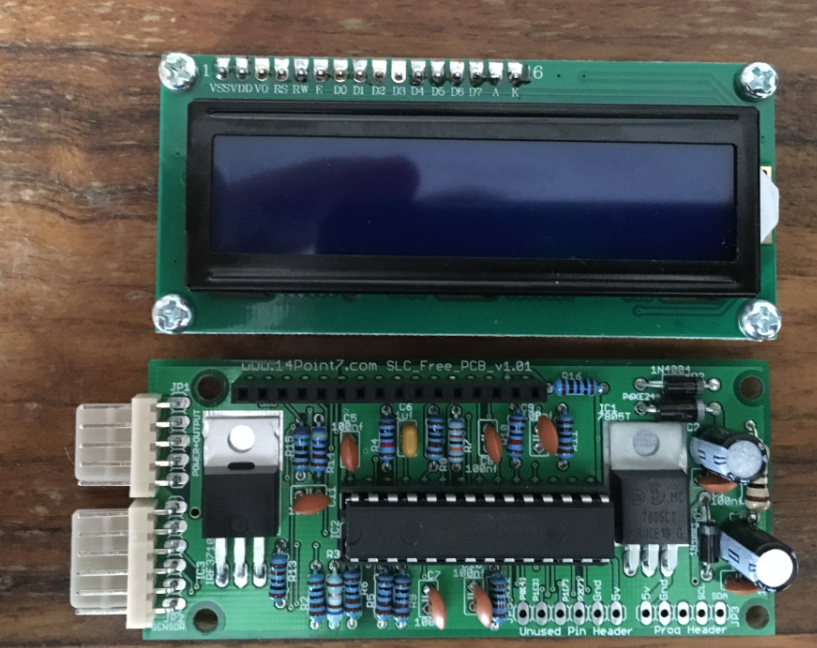
SLCfree.PNG (1.21 MiB) Viewed 7666 times

This is the case I am planning to build it into.
I will make up a secondary board that uses STAC64 series connectors (very cheap and seem quite nice), and include a power supply and map sensor on the secondary board.
case.PNG
case.PNG (2.18 MiB) Viewed 7666 times
This is the case, $14usd with free shipping
http://www.aliexpress.com/snapshot/7721761875.html?orderId=75629853953468

and a link to the connectors (~3$usd for the pcb connector, plug and pins)
http://nz.rs-online.com/web/p/automotive-connectors/7241374/
User avatar
AndreyB
Site Admin
Posts: 14331
Joined: Wed Aug 28, 2013 1:28 am
Location: Jersey City
Github Username: rusefillc
Slack: Andrey B

Re: Dial0's Projects

Post by AndreyB »

Just a tad jealous of your progress :) Thank you for all the links!
Very limited telepathic abilities - please post logs & tunes where appropriate - http://rusefi.com/s/questions

Always looking for C/C++/Java/PHP developers! Please help us see https://rusefi.com/s/howtocontribute
User avatar
kb1gtt
contributor
contributor
Posts: 3758
Joined: Tue Sep 10, 2013 1:42 am
Location: ME of USA

Re: Dial0's Projects

Post by kb1gtt »

I like this connector, I wish I could find one that has some kind of sealed feature with a price that's similar to this.

I see the connector cost like this
$2.48usd PCB side 20pins http://www.mouser.com/ProductDetail/Molex/34691-0203/?qs=%2fha2pyFadujRXvlWZHajT2Ll8Hs3VRGyHjZfkjhZ89W88Zb8aTf4dQ%3d%3d
$0.10usd per harness pin http://www.mouser.com/ProductDetail/Molex/34803-3212-Loose-Piece/?qs=%2fha2pyFadujyi6L%2fncT22PXnnj99Ex29%2feOar1h53chm%252bkXyUcEmuekpXUW%2fCXlk
$1.27usd for mating shell http://www.mouser.com/Search/ProductDetail.aspx?qs=z97Pd%2ft43AZV4y2JvfzeXw%3d%3d

So a total cost for 20 pins is 2.48 + 1.27 + 0.10*20 = $5.75usd that's $0.29 per pin, which isn't bad.

About the hi/lo, I swear I wrote down the numbers somewhere, but I can't seem to find it now. From memory that's 0.125A per channel, assuming both channels are being used, so 0.25A per chip. Also that's continuous conducting and steady state. In reality your probably not going to be 100% duty, and your probably not going to be at the max ambient, with no air flow, and doing this long enough to heat up the thermal mass of the PCB. So real numbers above 0.125 are likely, but under worst case predictions, you should be safe with 0.125A drive. If you exceed this current it's probably a good idea to do some testing to see if you are going to overheat or not.

I'm not quite sure about the startup state, I seem to recall the STM's default start state was weak pull down, then switched to drive high and low after initialization. However that's from memory, so it could be wrong.
Welcome to the friendlier side of internet crazy :)
Post Reply