Page 2 of 6
Re: 2004 Mazda MX5 1.8 VVT
Posted: Thu Apr 11, 2019 1:03 am
by AndreyB
Now I am jealous

Re: 2004 Mazda MX5 1.8 VVT
Posted: Thu Apr 11, 2019 5:11 pm
by Crazy Striker
I have a problem.
My crank and cam was not working when tested on the car.
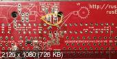
Trying to solve the problem I burned tracks on the board where the VR/HALL chip goes.

- 1555002519666775724994679392024.jpg (3.2 MiB) Viewed 21192 times
I think it will be possible to wire the hall inputs directly to the board without this Chip, am I wrong ?
Should I connect them to the CAM 1ST and CRANK 2ND headers ?
However I get the board to boot up, the analog inputs seem to work and I can start the radiator fan through console.
Thanks
Re: 2004 Mazda MX5 1.8 VVT
Posted: Thu Apr 11, 2019 5:16 pm
by kb1gtt
If you have hall, and if you can make it run with 5V, you can likely bypass the 9926 and connect that signal direct to the STM32.
Re: 2004 Mazda MX5 1.8 VVT
Posted: Thu Apr 11, 2019 5:21 pm
by Crazy Striker
Cam and crank sensor are powered by 12v but their output oscillate between 0 and 5 so it should be okay then
Re: 2004 Mazda MX5 1.8 VVT
Posted: Thu Apr 11, 2019 6:06 pm
by Crazy Striker
Tried it directly connected to the board, no more luck with a signal. With the engine sniffer I can't pick up anything when cranking.
Re: 2004 Mazda MX5 1.8 VVT
Posted: Thu Apr 11, 2019 6:46 pm
by Crazy Striker
Maybe should I power the main relay. I don't know if it works
Re: 2004 Mazda MX5 1.8 VVT
Posted: Thu Apr 11, 2019 8:22 pm
by Crazy Striker
So what works so far :
Power to ECU
Communication with computer (TS and Dev console)
Analog inputs : IAT, CLT, TPS
I did not plug the outputs yet.
Could not get the crank sensor and cam sensor to work through the MAX chip.
Tried to connect it after the max chip, did not work.
Will try tomorrow morning to connect it directly at JP04 and JP05 after the jumpers (which I removed)
I checked continuity between JP04 and JP05 and the discovery and it is OK.
Maybe I still need a pull-up to this signal ?
The car is still running fine with stock ECU
I will receive my MAP sensor soon so I will be able to start the car, except if you know how to start it with MAF.
Cheers
Gwendal
Re: 2004 Mazda MX5 1.8 VVT
Posted: Thu Apr 11, 2019 9:06 pm
by Abricos
Maybe you want check maybe you need this jumper ...
Re: 2004 Mazda MX5 1.8 VVT
Posted: Thu Apr 11, 2019 10:40 pm
by kb1gtt
If you have 0V to 5V on your signal wire, then yes you should be OK. The STM32 is 5V tolerant on the digital IO pins. Can I confirm you measured the 5V when it was only connected to a DMM? AKA I expect the rusEFI board will limit you to 5V. If the board was connected it may have caused you to think it was 5V when it was really trying to drive to 12V. So just to make sure we are clear, check the 5V when your DMM is the only thing connected from the signal wire to GND.
Re: 2004 Mazda MX5 1.8 VVT
Posted: Fri Apr 12, 2019 2:02 am
by AndreyB
Jared, can you please make a sticky note somewhere "Mazda MX5 = Hall"?
It's "Hall" maybe not really Hall but that's details.
Crazy Striker

You have a second route - you can feed signals via op-amp channels #9 and #11. Frankenso has jumpers to route these op-amp outputs into same CAM and CRANK pins of stm32.
I assume op-amps are needed and you better do not feed "Hall" output directly into stm32.
Re: 2004 Mazda MX5 1.8 VVT
Posted: Fri Apr 12, 2019 2:03 am
by AndreyB
PS: this is a route less traveled, you now have three people telling you to do three different things. Please take you time to understand your plan and do not rush into soldering.
Re: 2004 Mazda MX5 1.8 VVT
Posted: Fri Apr 12, 2019 5:34 am
by Crazy Striker
Ok so in order to use the opamps :
I connect the cam and crank signal to analog inputs 9 and 11.
The output of 9 and 11 channels have a jumper which normally connect them to PA7 and PC4.
I do not populate the jumper but I use a wire going from their opamps side to the Cam and Crank inputs on the discovery side of JP04 and JP 05. And then it should be OK

- IMG_20190412_072938__01.jpg (4.58 MiB) Viewed 21155 times
Re: 2004 Mazda MX5 1.8 VVT
Posted: Fri Apr 12, 2019 8:02 am
by kb1gtt
I agree, get input signals working, then connect outputs only after the inputs are working. When you do the outputs, I suggest doing spark first. It's hard to hydrolock your engine with spark.
The opamp is useful if you have a 12V hall or other 12V digital signal. It will allow you to convert from 12V to the logic level of the STM32. This op-amp circuit will register as a 1 somewhere around 3V and this circuit protects well above 14V. So any voltage between around 3V and 14V will indicate as a "1" on the STM's input pin. As well a voltage below about 1V should register as a "0" on STM's input pin. You should be OK connecting a 5V or 12V hall to this input circuit.
Beware the low pass filtering on the opamp circuit. You may need to remove or change some caps and resistors. AKA C310 and R310 (or C290 and R290) probably want to be removed. If this proves to be noisy, we may need to install a small cap for C310 and C290. For now try it with out these caps.
Hmmm, there is a chance that you are OK with R310 and R290. If they are already installed, please leave them. If they are not installed, then please leave them removed. It appears they are already installed, so leave them for now.
If C310 and C290 are installed, those will need to be removed.
How close to hall is this circuit? Can the engine be rotated by hand and get it to sit at a 0 or a 1? If it can work at these low RPM's then perhaps before soldering caps and resistors, try connecting it and seeing if you can get a 0 and 1 when rotating it by hand.
Also I believe you are looking for both CAM and CRANK signals.
Does
@ agree with these next steps
-- Install blue and green jumper wires as shown in picture.
-- Rotate by hand, validate 0 and 1 in the console. Verify 0V and 5V with a multi-meter.
-- Remove C310 and C290
-- Attempt to capture cranking signal while cranking.
My lack of sleep is perhaps working in your benefit. Here's hoping my post makes sense.
Re: 2004 Mazda MX5 1.8 VVT
Posted: Fri Apr 12, 2019 8:47 am
by Crazy Striker
Yes !!!
I have trigger signal and RPM showing during cranking

So happy now thank you !
Re: 2004 Mazda MX5 1.8 VVT
Posted: Fri Apr 12, 2019 8:51 am
by kb1gtt
If we look for the op-amp circuit to pass 0.1 degree's of accuracy, at 6kRPM the filter needs to be at least ....
6kRPM (1M/60S) (3600 ticks / R) = 360k ticks/second. So the low pass filter knee should be at least 360k Hz.
With the 1kHz filter, we could expect up to
1k ticks/seconds (60seconds/1M) (1R / 3600ticks) = 16 RPM. so the 1kHz is simply not going to work. Maybe enough signal will get through after the knee, but phase shift is a bugger, so lets avoid this region.
Hmm, if we use the 47pF like R352 on PG7, with 10.1k ohms, then the cut off is 335k. This would reduce noise issues.
http://sim.okawa-denshi.jp/en/CRtool.php
What is your configuration? AKA what resistors and caps are installed at this point in time?
Re: 2004 Mazda MX5 1.8 VVT
Posted: Fri Apr 12, 2019 10:22 am
by Crazy Striker
Input 9 and 11 are filtered to 100khz according to the schematics. I have 0.01uF for both filters and 100 ohms. Maybe should I use 0.0022uF for these as this would raise filter knee to 400khz approx.
Re: 2004 Mazda MX5 1.8 VVT
Posted: Fri Apr 12, 2019 11:16 am
by kb1gtt
Schematic should be updated once
@ gets a minute to migrate my most recent changes. The lower cap is better. Also the 0.1 degree resolution might not be required. I just did that as I was looking for the filter to not be the limiting factor in most setups. So your small cap is likely a step in the right direction. For now I would say remove it and your probably fine for the time being. Also keep in mind it's probably 10K plus 100 ohms. So 10.1k ohms.
Re: 2004 Mazda MX5 1.8 VVT
Posted: Fri Apr 12, 2019 11:21 am
by Crazy Striker
Ok so I remove the filter stage before the OPAMP.
Thank you very much

Re: 2004 Mazda MX5 1.8 VVT
Posted: Sat Apr 13, 2019 1:45 pm
by Crazy Striker
For the logic level jumpers on the high drivers side, which ones should I choose for the VVT miata ? Should I set all the drivers to 12V ?
Thanks !
Re: 2004 Mazda MX5 1.8 VVT
Posted: Sat Apr 13, 2019 9:15 pm
by AndreyB
Re: 2004 Mazda MX5 1.8 VVT
Posted: Sun Apr 14, 2019 2:18 pm
by Crazy Striker
Thank you very much.
I'm now looking for best config for first cranking.
You can find attached screenshots of many TS windows and the tune. What do you think of it. Have I missed something in the config ?
Re: 2004 Mazda MX5 1.8 VVT
Posted: Sun Apr 14, 2019 2:32 pm
by AndreyB
i would not be able to go other since thats a big effort to do it right and I am not too experienced anyway
just to confirm, did you consider using my nb2 preser which is available in the firmware? i am afraid that the presets are not too visible or popular but that could be a way to navigate this complexity
also engines are pretty sturdy, i have not yet destroyed one single engine. we have only burned coils
Re: 2004 Mazda MX5 1.8 VVT
Posted: Sun Apr 14, 2019 2:34 pm
by Crazy Striker
Yes I choose the NB2 preset in tunerstudio, just that I don't know which values are affected. For the Timing and VE tables I took them from a tune I found on the forum, but for the AFR target I used a generator which tend to be on the safe and rich side, and not tuned for economy X)
Re: 2004 Mazda MX5 1.8 VVT
Posted: Sun Apr 14, 2019 2:36 pm
by AndreyB
presets buttons overrides all values in controller. you need to reboot ecu and reconnect after the button is pushed
Re: 2004 Mazda MX5 1.8 VVT
Posted: Mon Apr 15, 2019 5:51 pm
by Crazy Striker
Just received my MAP sensor, a Chinese knockoff Wichita seem of a good quality and the wideband signal. I also wired the baro sensor which is present on stock Miata (thought of using it as MAP but no need for it now).
Tomorrow I will try to fire up the car for a first drive.
I was wondering what flow should I specify for injectors as I have mk2.5 purple ones, which are rated at 265cc/min but for 3 bars. Stock pressure is closest to 4 bars so should I recalculate the flow ?
Thanks
Gwendal
Re: 2004 Mazda MX5 1.8 VVT
Posted: Tue Apr 16, 2019 1:20 pm
by Crazy Striker
First startup is not so right, I can only get some very very loud pops and the engine is sometimes definitely firing but I could not build enough revs.
Maybe my trigger offset needs to be configured.
I've tested with warm engine (88°C CLT and no more luck)
Re: 2004 Mazda MX5 1.8 VVT
Posted: Tue Apr 16, 2019 1:37 pm
by Crazy Striker
Spark is working, injectors are working but I couldn't verify IAC is working.
Re: 2004 Mazda MX5 1.8 VVT
Posted: Tue Apr 16, 2019 5:46 pm
by Crazy Striker
I checked all the wiring and used the NB2 preset. Got the car on the edge of running but not running.
I tried to change some settings, as the cranking pulse duration and the cranking advance but I couldn't get it to work.
Because I'm using the OPAMP, should I invert the inputs in the configuration of something like that.
Should I specify an offset in the trigger configuration ?
It's so frustrating being so close

Thank you
Gwendal
Re: 2004 Mazda MX5 1.8 VVT
Posted: Tue Apr 16, 2019 7:32 pm
by AndreyB
opamp onverted maybe.
can you disable fuel and record a vide of RPM gauge while crankung? does it show a healthy steady value? is engine sniffer on console shows reliable steady spark schedule?
Re: 2004 Mazda MX5 1.8 VVT
Posted: Tue Apr 16, 2019 7:38 pm
by Crazy Striker
https://youtu.be/yva_zOCNAzU
RPM reads steady around 200-210 RPM during cranking
