Based on my analysis of the schematics it looks like these should both just get 12V from pin 1B.
Is this correct?
Please elaborate what are your arguments for that? Does not sound right to be honest but please remember that it has been forever or never that I had NB1.
While you say "NB" here, you have NB1 and I have NB2
The wiring schematic for my 99 NB1 shows 3 wires each to the hall effect crank and cam sensors: 12V, Gnd, signal.
The board requires 2 unique inputs for the crank and cam pins (2A and 2B for crank) and (2C and 2D for cam)
So far I have populated 2B and 2D with the signal from each sensor, and so to me the logical answer for the 2A and 2C is 12V since ground is already coming from pins 3A-3D.
In case of Hall sensors, for each channel you have one signal and you simply do not touch the other wire, you leave it not connected to anything.
You car harness powers your sensors and rusEfi or ECU has nothing to do with that.
2B and 2D with the signal from each sensor YES.
2A and 2C just leave them not connected to anything. The board would actually make them have 2.5v but again - please do not wire to anything.
Making really good progress here. Just about done with the bulk of the repinning work, but still need to figure out a few more loose ends.
Done for today but will hopefully get back on it tomorrow.
Can you share the info you promised about the IAC solenoid issue?
In other words, where should the diodes be installed that came with the board?
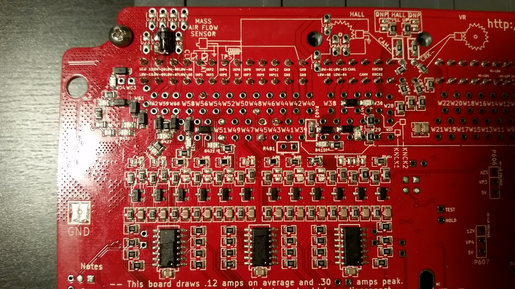
Those are the cam and crank signals from the harness(2H and 2J) going to 2B and 2D on the board per our earlier discussion.
It was just easier to access from the back side since the connector pins were in the way even though I cut them.
So in the process of remapping the pins on my NB1 to the NA configuration, I created the table that is attached here.
Until I've tested everything, I cannot say that this all correct.
I started with what is available on the wiki page https://rusefi.com/wiki/index.php?title=Vehicle:Mazda_Miata_1999, and fixed a few mistakes, namely pins W45 and W46, and finished populating it with a little more detail.
I only say that these were mistakes based on my reading of the wiring schematics, but I may find otherwise once I actually test my work.
Here is what is so far the finished product with all the pins cross wired to the NA configuration.(until I test it and find mistakes)
My intention is to maintain as much stock functionality as possible (AC, etc).
Now it's time to start the testing and implementation process.
I welcome any tips for bench testing.
I feel like I have a general idea of how to test some outputs, but might be way off base too.
For example, I will test the injector drivers by wiring an injector to the pin on the connector and stimulate the board with console.
For inputs, I will simulate a sensor signal with a resistor and watch the reading change with TS.
As far as setting up the crank trigger offset, I'm told I need a timing light.
Does 0 degrees of offset during cranking as set by TS not equate to 0 degrees of actual spark advance(or whatever spark advance is desired)?
Why is a timing light needed for a computor controlled system? I see why this would be needed with a distributor system, but am not connecting the dots here for my system.
I have a strange problem with the micro USB port on the discovery board...
When I connect the micro USB cable, it doesn't seem to provide any power to the board, and therefore doesnt allow a connection.
If I plug in the Mini USB cable on the opposite end of the board and connect it to a standalone power source, the board gets powered.
I can then connect the micro USB cable and connect to the board through TS or Console.
So basically, it looks like the board isn't getting power through the micro USB.
Why is a timing light needed for a computer controlled system? I see why this would be needed with a distributor system, but am not connecting the dots here for my system.
A timing light is not needed with your NB hardware since in your case position of OEM sensors is well known.
Contrary to Miata NA where position sensor could be rotated a bit. Contrary to unknown random car where 60/2 position is unknown.
Here are my tunes I have used in past. I don't know if these are any good for you. Everything is mixed. There are some with the original trigger wheel setup and some with the 36/1 setup.
Here are my tunes I have used in past. I don't know if these are any good for you. Everything is mixed. There are some with the original trigger wheel setup and some with the 36/1 setup.
I hope you find them useful:
Thanks!
This will be very helpful!
The crank trigger offset is 369 degrees in your cal.
Is this about what I should expect for my car too, or was this with a different trigger wheel?
Last edited by scramblr on Fri Oct 04, 2019 7:43 pm, edited 1 time in total.
I'm finding a strange issue in TS where the VE table load axis is TPS, even though I have "Use TPS instead of Load for VE table" set to false.
When I open the cal that RadMx5 sent, the settings are exactly the same but the load Axis is MAP.
The only difference I can find is that it was an older firmware in his cal.
Is this a potential firmware issue, or am I missing a setting somewhere?
My .msq file is attached.
Attachments
[The extension msq has been deactivated and can no longer be displayed.]
TPSforLoadAxis.PNG (122.15 KiB) Viewed 24543 times
We have a usability issue Your TS project settings do not match rusEfi firmware settings. You need to make similar changes in two different windows while you are making a change
I need to mess with my IAC a little because I had to be a touch on the throttle to keep it running, but the spark and injection seem to be doing what they're supposed to.
Next step: install wideband and get it idling right.
There were no shortage of issues to work through for me!
I figured out that my injection stategy of injecting 1&3 and 2&4 at the same time was not going to work, so I had to switch to individual drivers for each injector.
I also burned out part of the pcb where pin 1B(ignition power) goes to the jumper.
I found that the wire I had in that jumper location was sticking out of the back of the board too far and made contact with the rear cover of the case, so when the case touched part of the frame under the dash it shorted that pin to gnd and fried the trace on the board.
Hard wired from the pin to the jumper and good to go now!
I'm having trouble with the alternator PID control.
With simple on/off mode, I get what seems to be appropriate behavaior: The battery voltage oscillates at the target voltage at the frequency I set for control frequency, and I can hear the alternator loading and unloading.
However, when I switch to PID control, I cannot get any alterator response.
I mess with all the PID settings, and still the alternator will not load up.
Any ideas?
Are there known issues with this feature?
I'm not sure if the on/off is working correctly, but it seems to be OK.
If I set the target voltage to 13 and the control period to something small like 10ms, it oscillates around 13.
It's not smooth and is a bit annoying since the engine will load and unload continuously, but works non the less.
I posted a log file if you're interested.
Also, I'm having trigger issues at rpms above 2k which prevents me from ever getting over 3k rpm.
At first I thought something was intervening, but I realized that the trigger is having issues.(again you can see in the attached data log)
When I try to log with console, I get an error that says "trigger error reading 6/8/0 expected 6/16/0" or something along those lines(going from memory)
Any thoughts on how to resolve this?
Attachments
[The extension msq has been deactivated and can no longer be displayed.]


