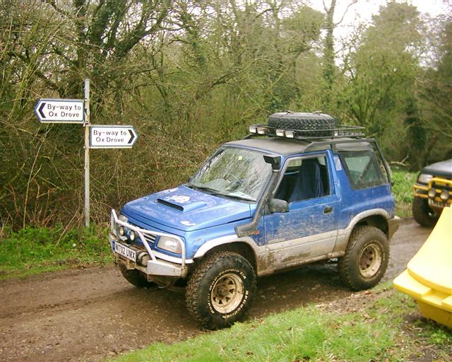
kb1gtt wrote:Those Suzuki's are nice. Small enough you can fit between trees, and when you get stuck it's easier to pull it out. Yet it's large enough you can do some nice weekend rock crawling.
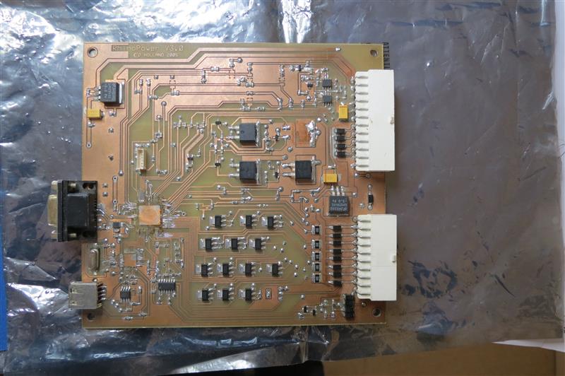
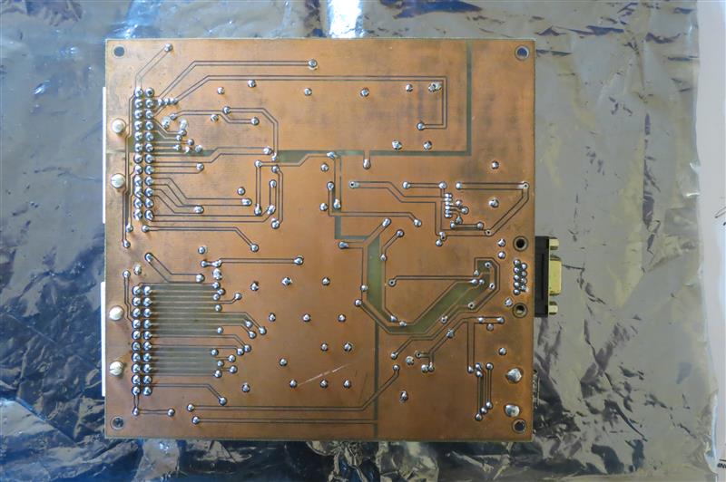
Is your PCB design something you can and are willing to share? If so I can offer a review to help make it better. If not, that's also cool. Just wanted to offer a second set of eyes.
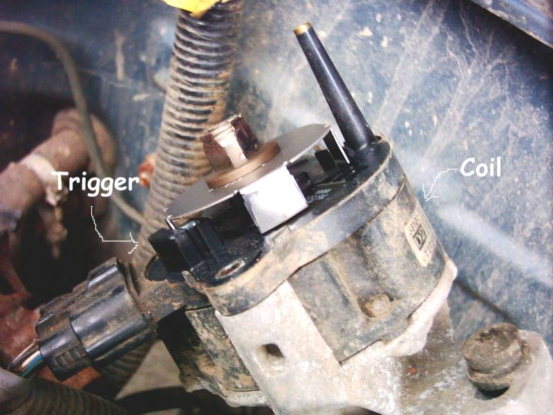
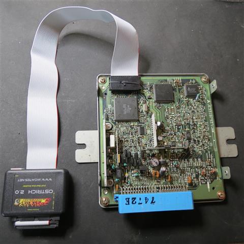
What's your general engine setup? Natural aspirated, with distributor, etc? Is that one injector in the throttle body? I generally don't expect lowZ on a 1.6 liter. Some years ago I helped develop a board that used LowZ, I a usable circuit done in KICAD, which could be handy if you want a PCB with native LowZ. Either that or you can use the JBPerf LowZ board to convert a HighZ to LowZ.
I used to drive it quite long distances, the longest trip was the Sweden Off Road Tour in 2002. I also have a Jimny which is my daily driver.
I will publish the schematics and PCB design, I will do some updating first.
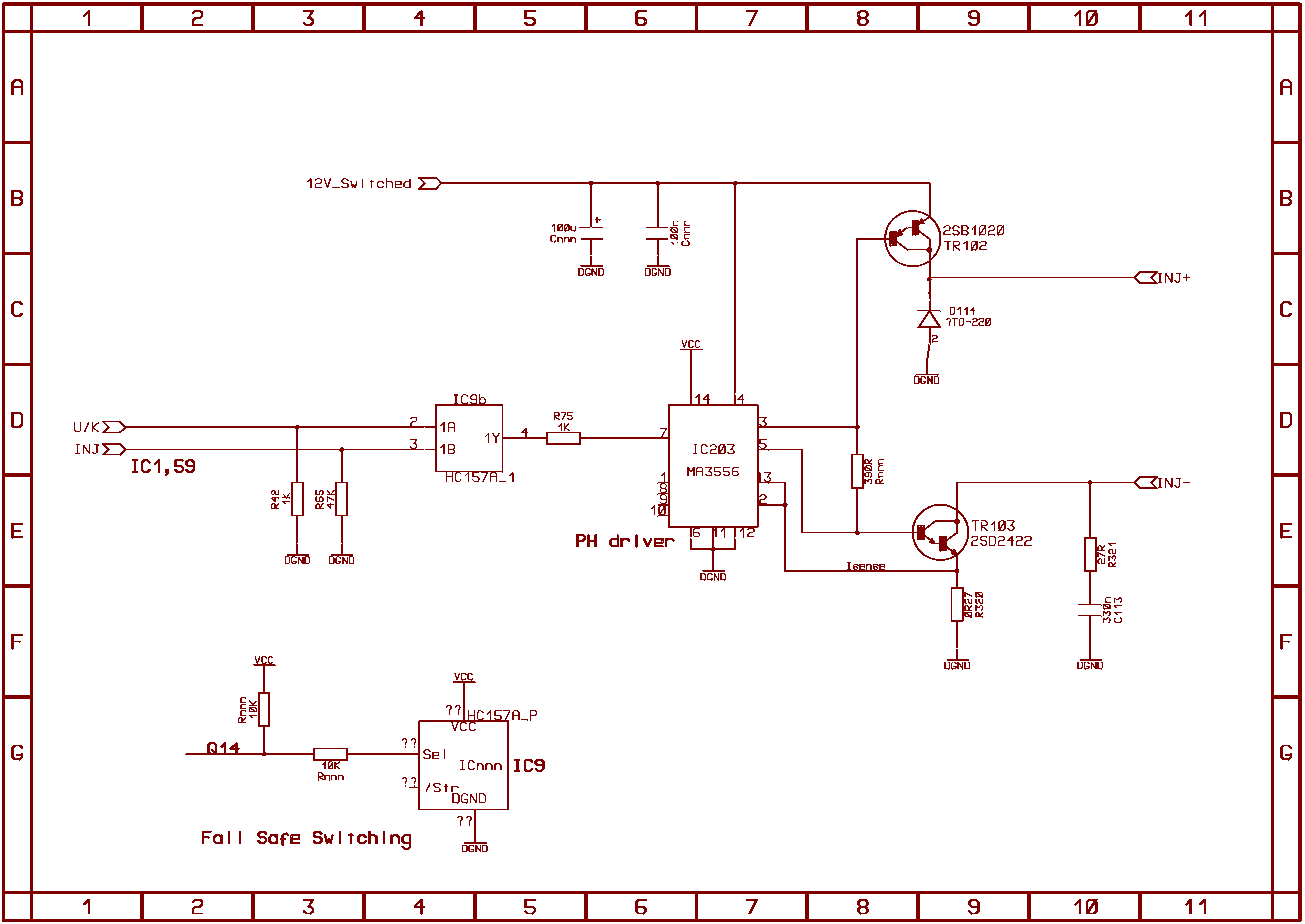
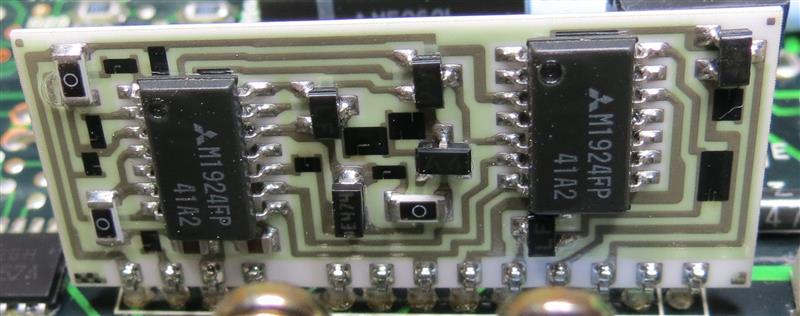
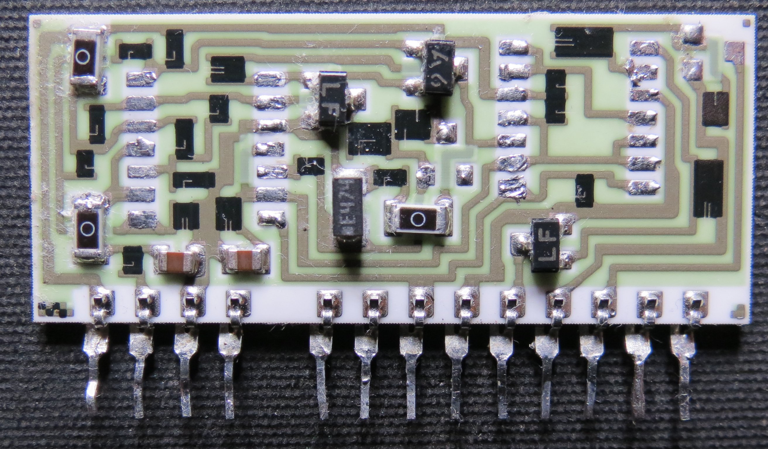
The engine is a N/A, single throttle body, single injector design, these were all low-z injectors. I've done a few low-z designs for OEM ECUs, there are many different configurations so I will need to think about how best to implement it, I don't need all the diagnostic capabilities that a modern ECU requires and the current ST processor doesn't have many pins. The stock ECU has a PH driver on a hybrid circuit which would be simple to re-use, I may use the original and then replace that with one of my own.


