
SVN repository
brain_board.zip
Schematic.pdf
also https://svn.code.sf.net/p/rusefi/code/trunk/hardware/brain_board_SD_Card_1/
https://oshpark.com/shared_projects/KCdXUUDD
BOM @ google
STM32™ microcontroller system memory boot mode
The STM32F40xxx/41xxx bootloader is activated by applying pattern1.
Pattern1 Boot0(Pin) = 1 and Boot1(Pin) = 0
Boot1=PB2=pad#37 is always GND on our board
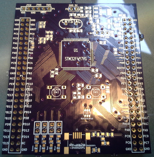
We need our own KiCad board with some stm32f4 chip in order to a) get the schematics ready 2) test my soldering skills
-1) for the first revision, we are targeting STM32F407VGT6 chip which is LQFP 100
0) dimensions: 57mm by 67mm
1) Should be an exact clone of stm32f4 from the pinout prospective
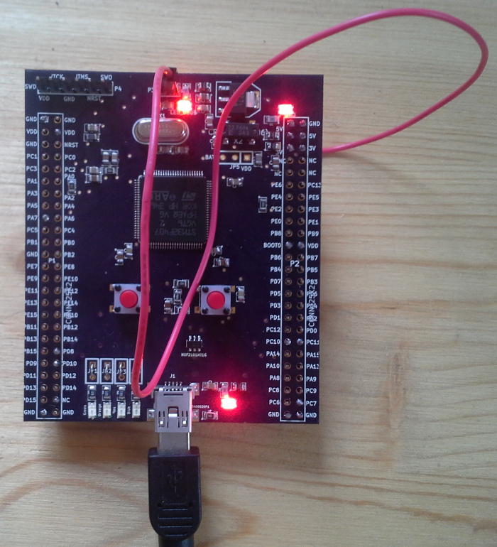
2) needs the same 4 LEDs
3) needs the reset button (?)
4) I guess 'user' button is not needed
5) should have some means of loading the firmware - could be UART or USB
For larger processor see http://rusefi.com/forum/viewtopic.php?f=4&t=749
ibom available at https://rusefi.com/docs/ibom/