[info] All rusefi boards are created modular, but some are....

Hardware inside and outside of the ECU
Post Reply
stefanst
contributor
contributor
Posts: 703
Joined: Wed Feb 17, 2016 12:24 am
Location: USA 08530

All rusefi boards are created modular, but some are....

Post by stefanst »

First: The current state of affairs is such that it appears primary development focus should be on software, rather than hardware. That being said, HW development is going on and appears to be going strong, so knowing where we're headed may help. The subject of HW concept has been brought up multiple times here with very good input from multiple sources. I would simply like to add what is my personal current preference. So please let me know where I'm wrong :D

Food for thought:
Current development seems to be focused on two different areas:
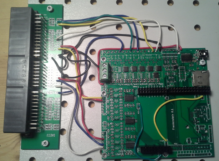
  • I/O circuits on seperate evaluation boards
  • Frankenso board (not a lot of development work seems to be going on right now)
The frankenso board is great at what it was designed for, but it has some shortcomings and will require revisions soon.
  • Lack of flexibility
  • Circuit layout not yet optimal
  • Designed for a specific brainboard
  • Designed for a specific type housing and connector
  • Limited real estate
  • Too large to reflow in a toaster-oven
  • ...
My preferred solution would be to have all the functional modules on sub-boards and the main board being essentially one big prototype area with predefined routes etc.

The I/O sub-boards should to a large extend have a unified architecture, so they can be replaced with one another easily. For example standard I/O boards for things like analog inputs, hi/lo drivers, lo-side power drivers, trigger sensors should all have the same base layout. My suggestion would be 4 inputs, 4 outputs, and the backbone connections: 5V, sanctioned 12V, Power GND and maybe signal GND. Another architecture would be needed for modules that communicate with the brain via SPI. I'm not sure if I would prefer the power supply as a separate module or directly on the main board.

I would also go back a step and have the main board without a vehicle connector and have the connector on a separate board that connects via pin headers or similar to the main board. This way customization for a specific vehicle is as simple as designing another patch/connector-board. No more messing around with jumper wires.

Advantages:
  • Revisions of single function modules don't require revisions to the whole main board
  • SMD assembly can be done on easily managed small boards using cheap Kapton stencils and toaster oven reflow (as long as all the SMD components are on the same surface)
  • Simplified carrier board
  • Mistakes are easier and cheaper to fix
  • Future proof
  • If you change cars, you don't have to remove jumpers and re-wire everything- just add a different connector-board
  • We could offer specific pre-designed packages for different vehicles straight out of the box
  • ...
This may of course have negative impact on the signal and electric noise side of the project- not my area of experience.
I also wonder, what type of connections to use between the function-modules and the main board. Simple pin-headers seem to be working well so far, even on racecars. On the other hand PCB-edge connectors have the appeal of having the sub-boards standing on edge and thus using the third dimension a little more efficiently.

This is just food for thought. But if that's a possible route to take, I would suggest to design future prototype function modules with the idea of compatibility with this concept in mind.
User avatar
AndreyB
Site Admin
Posts: 14334
Joined: Wed Aug 28, 2013 1:28 am
Location: Jersey City
Github Username: rusefillc
Slack: Andrey B

Re: All rusefi boards are created modular, but some are....

Post by AndreyB »

Technically all the components are already available as separate modules - see http://rusefi.com/forum/viewtopic.php?f=4&t=260 - the problem is that there is no unification in terms of how to connect these together and at the moment this gives us a nasty rats nest of wires like

Image

I like the idea of a carrier board but I have no idea how would it look like. Would we mount the small modules above & parallel to the carrier or would we stick them perpendicular to the carrier board? How would we inter-connect the boards - are we going to use wires? soldered single row 0.1" angled pins? some sort of a connector?
Very limited telepathic abilities - please post logs & tunes where appropriate - http://rusefi.com/s/questions

Always looking for C/C++/Java/PHP developers! Please help us see https://rusefi.com/s/howtocontribute
User avatar
kb1gtt
contributor
contributor
Posts: 3758
Joined: Tue Sep 10, 2013 1:42 am
Location: ME of USA

Re: All rusefi boards are created modular, but some are....

Post by kb1gtt »

Back some time ago, we started making littler boards. Eventually the little boards started to take shapes that could be ease-ish connected to STM brain board. This got nick named Frankeinstien, as it we were taking bits and pieces to make our monster. Eventually the layout was solid enough that we decided to make one PCB using an OEM ECU that can be found in junk yards. This was based on the Denso stuff, so which is where the Frankenso name came from.

Current cost break down is something like 25% PCB, 25% assembly, 40% for the harness / pigtail, and %10 for all the components put on the board. Perhaps slightly exaggerated, but not by much really. That connector is stupid expensive, followed closely by the PCB and assembly. If you make modules, you'll increase the PCB and assembly costs.

Stacked PCB's typically do have a lower performance than if on one board. The connectors add some interesting effects on the signals, as well you often are making longer and larger antennas. Your layout skills become more critical when dealing with a stack.

Everything can always be improved, and Frankenso is part of everything. I dream of a fiber optic back haul as a way to get the flexibility everyone want's / needs. It would allow modules to be placed close to things like coils, injectors, etc. This would help decrease radiated or conducted RF. Basically run 12V power to everything, and a fiber optic bus. If you need more injectors, install more modules, if you direct injection instead of manifold injection, use a different module for this one component, etc. See this thread for more on the concept. Getting such a concept to a prototype is a significant task.
http://rusefi.com/forum/viewtopic.php?f=4&t=412&p=4565

I also dream of a module that functions as an engine simulator. AKA leave in an OEM ECU, but run the engine with rusEFI. Then send simulation signals to the original ECU which then allows gauges, transmission control, etc to function.

A key lump in the development carpet is getting russian physical hardware to work against. He's got limited test mules, which limits what he can do in software.
Welcome to the friendlier side of internet crazy :)
klyttle
Posts: 19
Joined: Fri Jan 02, 2015 9:47 pm

Re: All rusefi boards are created modular, but some are....

Post by klyttle »

Is this a good time (and thread) to bring up my favorite subject once again? Hint: see link below:

http://www.embedded.com/electronics-blogs/max-unleashed-and-unfettered/4438849/Xilinx-Targets-Embedded-Software-Developers-with-SDSoC

It comes down to this question: What is rusEFI? Sure, hardware plays a critical role, but hardware can change to more advanced specs over time; it's the software that Andre has been developing over these past few years is what's really important, IMHO.

So, what do you all think? Is it time for something like this, or not yet?
User avatar
AndreyB
Site Admin
Posts: 14334
Joined: Wed Aug 28, 2013 1:28 am
Location: Jersey City
Github Username: rusefillc
Slack: Andrey B

Re: All rusefi boards are created modular, but some are....

Post by AndreyB »

klyttle wrote:What is rusEFI?
rusEFI is only possible because of http://www.chibios.org/ and mostly because of ChibiOS Hardware Abstraction Layer. Same as rusEfi, Chibios is a small group of crazy people so while they have HAL for a number of architectures, the stm32f* ports are the most mature. So far, ChibiOS is the only micro-controller environment where a lazy high-level developer can survive.
Very limited telepathic abilities - please post logs & tunes where appropriate - http://rusefi.com/s/questions

Always looking for C/C++/Java/PHP developers! Please help us see https://rusefi.com/s/howtocontribute
User avatar
kb1gtt
contributor
contributor
Posts: 3758
Joined: Tue Sep 10, 2013 1:42 am
Location: ME of USA

Re: All rusefi boards are created modular, but some are....

Post by kb1gtt »

Those kind of posts need a warning. I call them Jared Porn.

While it is really cool, the problem is that it's expensive and complicated. We have limited time and finical resources. Even with a more simple and more common development platform, there are very few contributors. It's mostly been me and russian, with a hand full of occasional patches. So it's really cool, but unfortunately we have a platform that has more than enough capabilities for very low $.
Welcome to the friendlier side of internet crazy :)
User avatar
AndreyB
Site Admin
Posts: 14334
Joined: Wed Aug 28, 2013 1:28 am
Location: Jersey City
Github Username: rusefillc
Slack: Andrey B

Re: All rusefi boards are created modular, but some are....

Post by AndreyB »

If only STM32F429IDISCOVERY were a 176 board :(

Unfortunately STM32F429IDISCOVERY uses a 144 pin version of the chip, so with about 35 pins used by the SDRAM chip it's not a lot of extra i-o pins.
Very limited telepathic abilities - please post logs & tunes where appropriate - http://rusefi.com/s/questions

Always looking for C/C++/Java/PHP developers! Please help us see https://rusefi.com/s/howtocontribute
stefanst
contributor
contributor
Posts: 703
Joined: Wed Feb 17, 2016 12:24 am
Location: USA 08530

Re: All rusefi boards are created modular, but some are....

Post by stefanst »

First to address the issue with the development cars:

I have a '99 Miata that already ran on the Frankenso and I hope to switch it over completely from Megasquirt by the end of April. The MS that gets freed up by that will then go into my 2003 Miata, so I can learn about tuning VVT. Once I understand to some degree, what I'm doing with that, I'd like to switch the '03 over to rusefi as well and sell my Megasquirt.
At that point we should have all or nearly all generations of Miatas ( NA 1.6, NA 1.8, NB1 and NB2) running on rusefi. I think the Miata-crowd would be the first to adapt, since Miata-racers are often the ones with the lowest budget and a competitive ECU at less than half the cost of a Megasquirt would be attractive to them. After that I would look at other popular low-budget racecars, maybe E30 BMWs. Offering a custom display option would probably also be interesting to the racing-crowd.

I would be glad to assist with the HW work if needed- just started using KiCAD and like all other packages it has some very annoying quirks, but is quite stable and seems fairly usable so far. Even though my electronics skills aren't the greatest- I'm a mechanical engineer after all- it would maybe a little help on the HW side of things.

At this point my suggestion was that we should look at unifying the footprint for all future test-boards, so they can be interchangeable- at least as much as possible. If the next iteration of the frankenso would then have a few slots open that would accept these unified boards, testing would be a lot easier. So this would really not require any additional development effort, it would just require an upfront discussion on what to standardize on.

@ brought up the point on what connectors to use and how to connect to the board. I personally am not a fan of spring-loaded connectors, especially in conjunction with vibration, but so far they seem to have been working OK for the brainboards. An as far as I know, all generations of the Megasquirt prior to the MS Pro use sockets for processor or expansion port connections with no ill effect. My personal preference would be using PCB edge connectors (like computer expansion cards), so we could just plug the module-boards into the main-board, without even having to solder headers to the modules. We'd also gain the use of previously unused vertical space. Not sure if there is a good, affordable source for this type connector though. If we're going with a scheme for 4 I/O, we'd need 5 high current pins and the rest could be low-current. Also the mechanical connection needs to be investigated. DNF or losing a race because a daughtercard in your ECU has fallen out would truly suck.

On the antenna issue: The only signals where I see potential for the antenna issue to be a problem on the boards are VR sensors. Most harnesses that I've seen don't even shield any of the other signals, so there you have some really strong antennas going!
One thing I personally would never want on the main board is an igniter. Nasty RF interference coming off of one of these....

So is there any reason to not try and come up with a standard format for future modules?
User avatar
AndreyB
Site Admin
Posts: 14334
Joined: Wed Aug 28, 2013 1:28 am
Location: Jersey City
Github Username: rusefillc
Slack: Andrey B

Re: All rusefi boards are created modular, but some are....

Post by AndreyB »

Is there really a use-case for removable, not soldered connection between the carrier board and a module? Typical ECU case would allow the vertical module to be about 3cm/1.25" so not much space really available for the connector.

I can see the benefit of using different modules so that one can only mount the modules he needs.
optionable modules I can think of are
1) on-board igniter module - between 2 and 8 of these
2) additional low-side drivers - 12 low side is not a lot
3) stepper idle valve module

that's not a lot but at least these ones could be unified.

Analog inputs as modules I do not really see a use-case. stm32 can only support up to 12-16 analog inputs, with the 4 channel op-amps... we can kind of have the bare minimum of 4 channels on the carrier board with the rest on add-on modules.

I have no idea how to make a nicer harness connector module. We have a problem that Miata NA and Miata NB have different pinout and the current solution is a rat's nest of wires. Are there any better ideas?

Maybe a connector board which is soldered above the carrier board which has the hard-wired rat's nest with traces instead of wires.
Very limited telepathic abilities - please post logs & tunes where appropriate - http://rusefi.com/s/questions

Always looking for C/C++/Java/PHP developers! Please help us see https://rusefi.com/s/howtocontribute
stefanst
contributor
contributor
Posts: 703
Joined: Wed Feb 17, 2016 12:24 am
Location: USA 08530

Re: All rusefi boards are created modular, but some are....

Post by stefanst »

russian wrote:Is there really a use-case for removable, not soldered connection between the carrier board and a module?
Definitely for development work- for production boards I would solder the connection. But if we're using pin-headers, either option is open.
russian wrote:Typical ECU case would allow the vertical module to be about 3cm/1.25" so not much space really available for the connector.
True. But a PCB edge connector, especially when soldered, shouldn't be taking up much real estate. But maybe we should stick with a horizontal/parallel board.
russian wrote:I have no idea how to make a nicer harness connector module. We have a problem that Miata NA and Miata NB have different pinout and the current solution is a rat's nest of wires. Are there any better ideas?

Maybe a connector board which is soldered above the carrier board which has the hard-wired rat's nest with traces instead of wires.
Exactly what I'm thinking. This would be easy enough, just made a little more complicated by the hardwired triggers in the current iteration of frankenso.
Maybe for the next evolution we could go back to a standard simple two-row connector at the end of the board, essentially requiring the use of an ECU connector adapter board. Price should not be very different from standard solution- maybe 4 more square inches (~ 25cm^2)of total board area for the overlap? Even at Oshpark prices that comes out to less than $7 per ECU.

I can't stress enough the fact how much easier it is (at least for me) to assemble small boards rather than large ones. I can easily do 4 3cm x 5cm boards with medium population under a microscope in an evening. While this is not production level efficiency, it's really not bad for development work. We're also looking at potential savings on scale: if we use three hi-current low-side drivers or hi-lo drivers per board on average, we have three times the number of identical boards at the same number of components. The higher the number of boards, the better the price per board.
User avatar
kb1gtt
contributor
contributor
Posts: 3758
Joined: Tue Sep 10, 2013 1:42 am
Location: ME of USA

Re: All rusefi boards are created modular, but some are....

Post by kb1gtt »

If we go optic bus via plastic wire that's cut with scissors, each board would be much smaller, and a mistake that breaks a board would be isolated to a lower $ if you have to scrap the board.

If we use some kind of back bone / data bus, we should consider a patter that has shields / caps / some existing boards that can be purchased. Either that or if we use an optical bus, it wouldn't matter. Just hook it all together and let packets steer the messages.
Welcome to the friendlier side of internet crazy :)
stefanst
contributor
contributor
Posts: 703
Joined: Wed Feb 17, 2016 12:24 am
Location: USA 08530

Re: All rusefi boards are created modular, but some are....

Post by stefanst »

kb1gtt wrote:If we go optic bus via plastic wire that's cut with scissors, each board would be much smaller, and a mistake that breaks a board would be isolated to a lower $ if you have to scrap the board.
Progress is an amazing thing. Last time I dealt with fiberoptics for data transmission (on analyzers), the plastic fibers had to be cut with specialized cutting tools- if I remember properly they actually used a diamond for the cutting. Then if it didn't work you could polish the end of the fiber....

A bus system is certainly interesting. Keeps the length of antenna that is the wiring loom to a minimum, on the other hand it also requires all the modules to be able to survive inside the engine bay.

But that's all going just a wee-bit beyond the original intent behind starting this thread- standardizing a layout for the future development modules.
User avatar
kb1gtt
contributor
contributor
Posts: 3758
Joined: Tue Sep 10, 2013 1:42 am
Location: ME of USA

Re: All rusefi boards are created modular, but some are....

Post by kb1gtt »

Oddly enough, that fiber optic bus was something I learned about back in 1999. It's low speed, some kHz's of bandwidth. The polished stuff is multi mode, typically GHz bandwidths, that can run some 60 miles. This industrial fiber stuff is a different animal.

I think you are talking of something similar to this https://www.element14.com/community/docs/DOC-67919/l/freescale-tower-system-modular-development-platform
Welcome to the friendlier side of internet crazy :)
klyttle
Posts: 19
Joined: Fri Jan 02, 2015 9:47 pm

Re: All rusefi boards are created modular, but some are....

Post by klyttle »

kb1gtt wrote:Those kind of posts need a warning. I call them Jared Porn.

While it is really cool, the problem is that it's expensive and complicated. We have limited time and finical resources. Even with a more simple and more common development platform, there are very few contributors. It's mostly been me and russian, with a hand full of occasional patches. So it's really cool, but unfortunately we have a platform that has more than enough capabilities for very low $.
OK, so not yet then.

Another issue to contend with is space for the ECU itself. Whatever, modularization system you decide on, we don't want to exclude our 2-wheeler buddies, do we?
User avatar
AndreyB
Site Admin
Posts: 14334
Joined: Wed Aug 28, 2013 1:28 am
Location: Jersey City
Github Username: rusefillc
Slack: Andrey B

Re: All rusefi boards are created modular, but some are....

Post by AndreyB »

This satellite developed by students really reminds me of something...

http://spaceflight101.com/soyuz-lomonosov/samsat-218d/
Attachments
IMG_0425.jpg
IMG_0425.jpg (223.74 KiB) Viewed 11203 times
Very limited telepathic abilities - please post logs & tunes where appropriate - http://rusefi.com/s/questions

Always looking for C/C++/Java/PHP developers! Please help us see https://rusefi.com/s/howtocontribute
Post Reply