


set engine_type 22
(close console / powercycle rusEfi / connect console)
idleinfo
this should produce something similar to
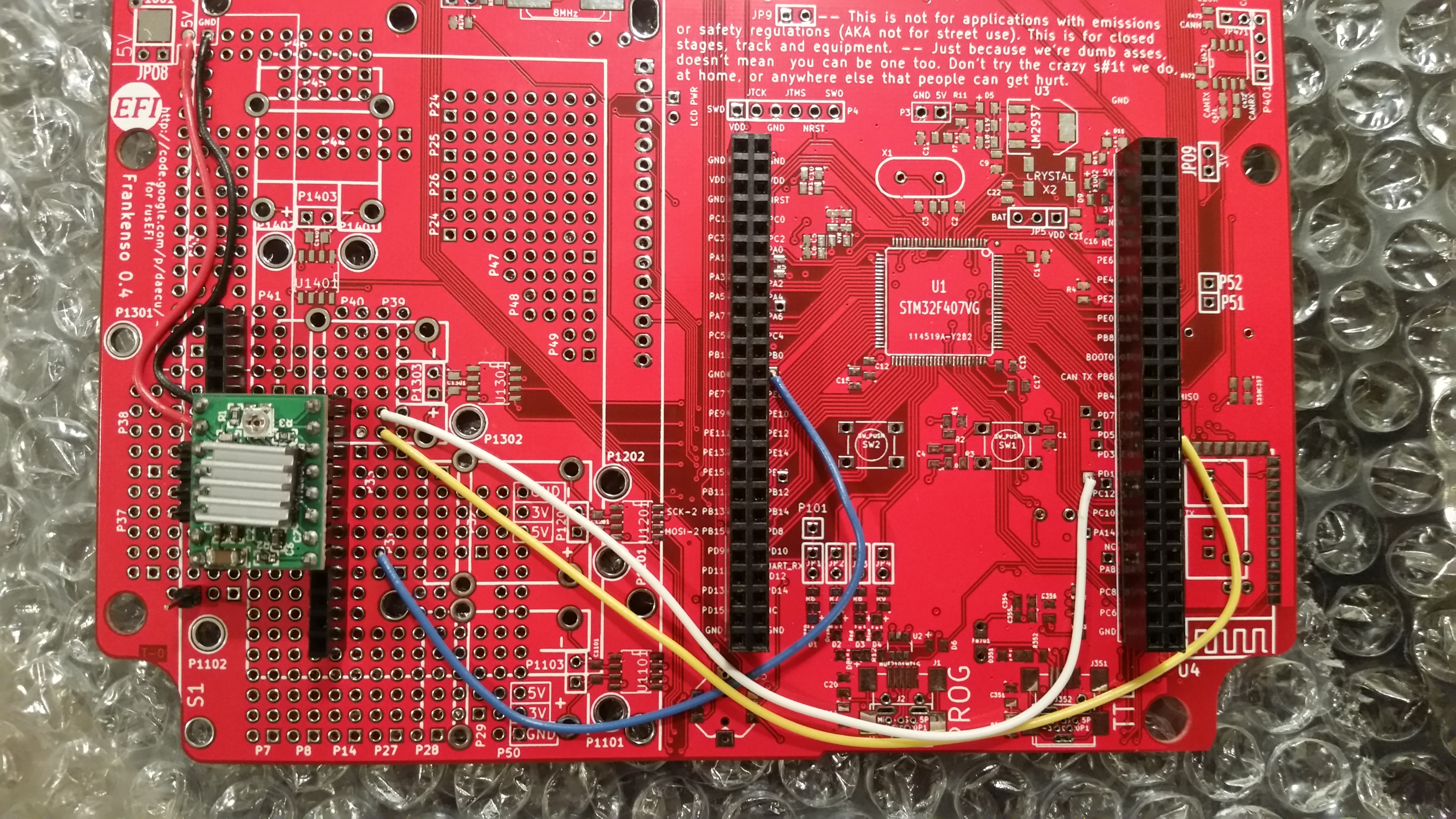
the code for this mentions recommended jumper wire colors2017-01-29 00_33: EngineState: directionPin=PD1 reactionTime=10.00
2017-01-29 00_33: EngineState: stepPin=PD6 steps=150
2017-01-29 00_33: EngineState: enablePin=PB1/0
Code: Select all
	boardConfiguration->idle.stepperDirectionPin = GPIOD_1; // top stepper drive pin, white wire recommended
	boardConfiguration->idle.stepperStepPin = GPIOD_6; // yellow wire recommended
	engineConfiguration->stepperEnablePin = GPIOB_1; // bottom stepper driver board pin, blue wire recommended

	boardConfiguration->triggerSimulatorPins[0] = GPIO_UNASSIGNED; // we want to avoid PD1 conflict
We still will need a 12v rail somewhere.
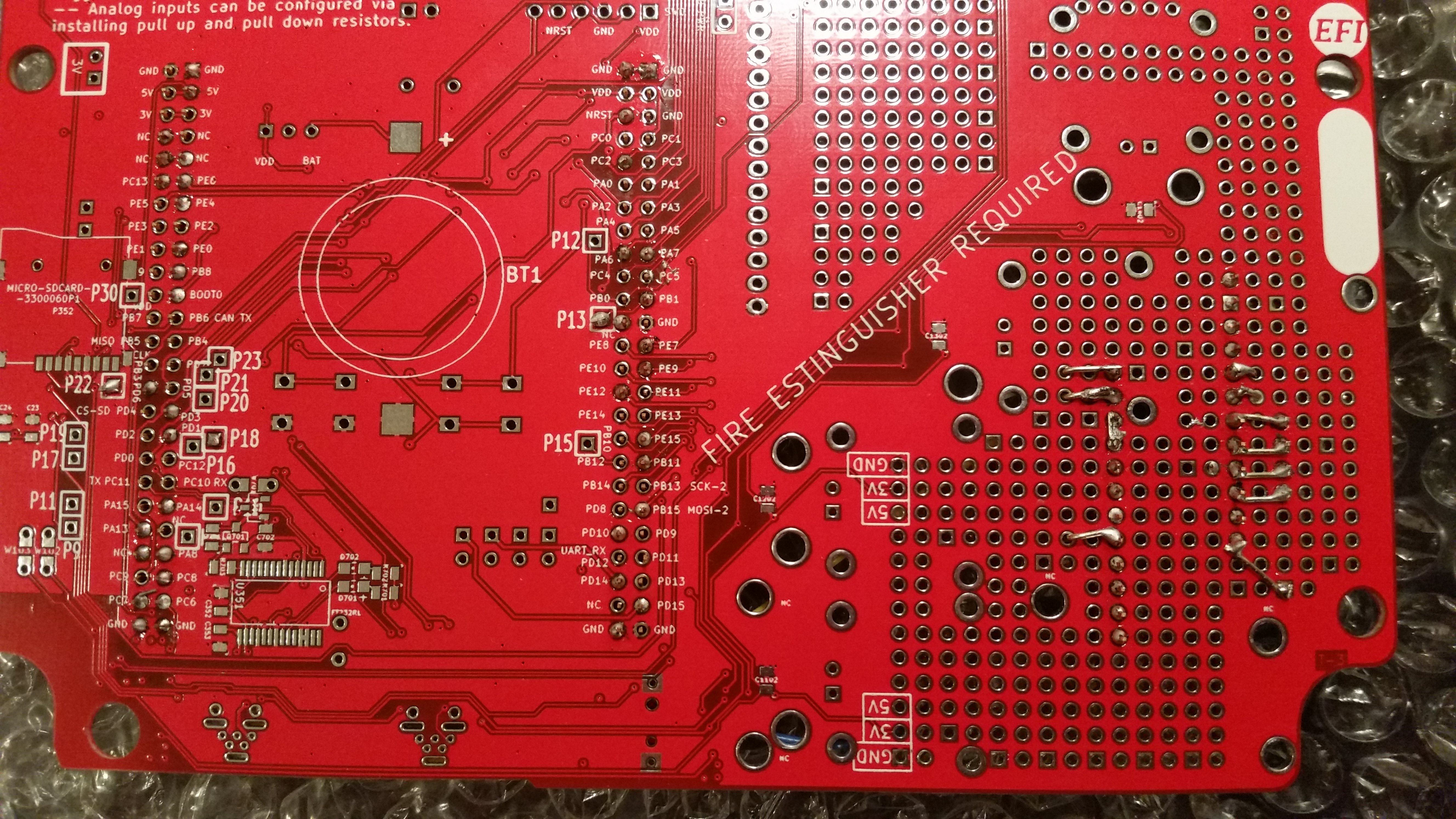
New action items for https://svn.code.sf.net/p/rusefi/code/trunk/hardware/frankenso/known_issues.txt111) GND and +12v rails? at least some 1.1mm holes in the prototyping area. Make holes larger for larger wires.
127) Add vias to button traces: PC8 PD11 PD10 (PD0 & PD2 already have those)
128) Add vias to most or all HL traces: PC7 PC9 PD8 PD9 PE8 PE10 PE12 PE14
See also http://rusefi.com/wiki/index.php?title=Hardware:Stepper_motor