

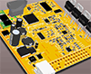


Let me introduce our new ECU board - Prometheus!
About Prometheus...
The project is born as a lightweight alternative for a transition from SECU-3i EFI to a more powerful and innovative hardware platform.
The idea is simple: take the existing SECU-3i housing and make a replacement of those two boards with one small PCB of the equal size.
And try to put inside everyting needed for a 4-cylinder fuel injection engine, including ready-to-use ignition drivers and even a bit more
The PCB is self inclusive, there is no need for STM32Discovery brain boards, external modules etc.
DISCLAIMER:
1. Prometheus board is an experimental hobby project. It's an independent design, not associated with the authors of rusEFI, but using rusEFI under the license. Please use only official rusEFI boards to avoid any problems - Frankenso, Frankenstein etc.
2. We're NOT experts in electronics or EFI, and we can NOT guarantee the operation of this board or correctness of the documentation. We are not liable for any damage caused by them.
3. The board is NOT universal, and has been designed for the limited specs of an "ordinary" 4-cylinder engine. We've made it for our own needs. It cannot do everything that official rusEFI boards do, and it's certainly NOT a complete replacement of them. See item 1.
4. The whole idea of 'Prometheus' project was to stuff "everything and the kitchen sink" densely into one small board, without any additional boards needed. It's a reckless experiment, for sure. But we never give up!
5. The current board revision was developed for manual pcb assembly only (no thermal relief requirements satisfied and so on), and for components available in our region, also taking into account the compatibility with SECU-3i peripherals.
Licensed under the TAPR Open Hardware License (http://www.tapr.org/OHL).
Special thanks to @Russian and @Kb1gtt for their brilliant work and inspiration!
Specs:
- * The newest STM32F469VI (freq 180 MHz, RAM 384 kB, 2 MB flash) in LQFP-100 package!
* Also there's an alternative: more affordable and cheaper STM32F405RG on the same board (double footprint!), not functionally constrained! (the package is only 64 pins - all pins are used!)
* MAX9926 - VR controller for crankshaft & camshaft
* TPIC8101 - knock sensor (detonation) controller
* DRV8825 - step motor controller for IAC (you can populate the IC or a fabricated Pololu module)
* CP2102 - cheap USB controller with ADUM1201 for electrical isolation
* SN65HVD230 - CAN-bus controller
* CJ125 - wideband oxygen sensor controller (highly experimental function!)
* VND14NV04 - onboard 4-channel protected injection drivers (high-impedance).
* BIP373 - onboard 4-channel "smart" protected ignition drivers. Direct drive of ignition coils!
* Analog sensor inputs for: MAP/MAF, IAT, CLT, TPS, oxygen sensor
* Low-side power protected outputs (including inductive loads): power relay, fuelpump, fan, starter block, oxygen sensor heater relays
* Protected signal outputs: Tachometer, CheckEngine, and also two additional signal inputs & two outputs
* Additional analog sensor input and ignition voltage measuring/detection input
* Bluetooth module HC-06 onboard (both SMD and TH versions supported)
* MicroSD memory card slot onboard
* Switching DC-DC 5V power supply onboard
* CR2032 holder for backup battery supply
* And all this fits the compact 4-layer PCB smaller than 93 x 100 mm!
- * There's no multi-pin connector on board, all pads are just for direct harness soldering.
* Two sided pcb assembly!
* All resistors and capacitors are not less than 0805.
* You'll need an external programmer (ST-LINK/V2 mini) for firmware update.
(more to come)
More photos and description will follow.
Stay tuned!
Thank you for your attention,
andreika.


