

Hi,
I have no output for the idle control. I have a BAC that standard on Mercedes. I wired it 12v one side and the other to INJ-01(PE6) and there is no output from rusefi.
I've tried PE5 and PB7 and there is no waveform output from rusefi.
I'm using an oscilloscope to test. When I try the idle valve test there is no change in the output.
Otherwise everything is working well.
[help needed] IDLE not working
-
gptech2444
- Posts: 46
- Joined: Mon Jan 22, 2018 9:01 pm
Re: IDLE not working
Ok, I got an output using PD7 LOW1a-03, looks like PE6 output is faulty with my board. And the test page output for idle valve does nothing.
The motor revs up but stalls as the rusefi over corrects. Are there known values that work for the PID on the Bosch valve?
The motor revs up but stalls as the rusefi over corrects. Are there known values that work for the PID on the Bosch valve?
-
gptech2444
- Posts: 46
- Joined: Mon Jan 22, 2018 9:01 pm
Re: IDLE not working
After a lot of trial and error I found settings that work ok.
There are still some issues though, there needs to be higher resolution for the output as it changes in whole percentage points, it needs tenth percentage steps.
There seems to be no way of opening the idle valve after a rev and the engine stalls as the idle valve stays on its lowest setting. The idle valve should open and close slowly down to its idle target.
There also needs to be a better explanation as to what each setting does, example what does "verbose" mean and what does it do?
- Attachments
-
- IMG_20180615_1715194.jpg (1.57 MiB) Viewed 10773 times
-
AndreyB

- Site Admin
- Posts: 14333
- Joined: Wed Aug 28, 2013 1:28 am
- Location: Jersey City
- Github Username: rusefillc
- Slack: Andrey B

Re: IDLE not working
resolution where? on some gauge or where _exactly_?gptech2444 wrote: ↑Fri Jun 15, 2018 7:54 amthere needs to be higher resolution for the output as it changes in whole percentage points, it needs tenth percentage steps.
which _exact_ setting do you think need more explanation?
Very limited telepathic abilities - please post logs & tunes where appropriate - http://rusefi.com/s/questions
Always looking for C/C++/Java/PHP developers! Please help us see https://rusefi.com/s/howtocontribute
Always looking for C/C++/Java/PHP developers! Please help us see https://rusefi.com/s/howtocontribute
-
gptech2444
- Posts: 46
- Joined: Mon Jan 22, 2018 9:01 pm
Re: IDLE not working
I thought I was clear that the idle output needs to be higher resolution than whole percentage points. The usable range on the Bosch idle valve is narrow, from about 46-60%.russian wrote: ↑Fri Jun 15, 2018 8:12 pmresolution where? on some gauge or where _exactly_?gptech2444 wrote: ↑Fri Jun 15, 2018 7:54 amthere needs to be higher resolution for the output as it changes in whole percentage points, it needs tenth percentage steps.
which _exact_ setting do you think need more explanation?
Or is the output to the valve higher resolution than what the gauge displays? ie gauge displays 50% but value going to the valve is 49.65%
As I said, what does "verbose" mean? Also "period(ms)" and "Offset" on the idle settings page.
I think there needs to be a damper delay after releasing the throttle so the motor doesn't undershoot the target idle and stall.
-
gptech2444
- Posts: 46
- Joined: Mon Jan 22, 2018 9:01 pm
Re: IDLE not working
Motec's approach to PID tuning.
- Attachments
-
- DTN0003_Introduction_to_PID_Control.pdf
- (42.08 KiB) Downloaded 331 times
-
AndreyB
- Site Admin
- Posts: 14333
- Joined: Wed Aug 28, 2013 1:28 am
- Location: Jersey City
- Github Username: rusefillc
- Slack: Andrey B
Re: IDLE not working
idle output is a float value with a lot of precision, it's the gauge which had no decimal ponits - one digit after the point added.
period, verbose and offset clarification added - let me know if it's not exactly undestandable or maybe suggest some better wording if you see what I mean but you think it could be expressed better?
https://github.com/rusefi/rusefi/commit/2235d03e1fb646cebfdf7f29991eb6f20ad4c64b
period, verbose and offset clarification added - let me know if it's not exactly undestandable or maybe suggest some better wording if you see what I mean but you think it could be expressed better?
https://github.com/rusefi/rusefi/commit/2235d03e1fb646cebfdf7f29991eb6f20ad4c64b
Very limited telepathic abilities - please post logs & tunes where appropriate - http://rusefi.com/s/questions
Always looking for C/C++/Java/PHP developers! Please help us see https://rusefi.com/s/howtocontribute
Always looking for C/C++/Java/PHP developers! Please help us see https://rusefi.com/s/howtocontribute

Re: IDLE not working
The PID is float, so the issue appears to be linearization. PID wants a linear input and a linear output. There are many forms of linearization. Some times it is simply scaling such that 0% = 20mS pulse, and 100% = 40mS pulse. In this case it appears you need a min pulse of XX mS, and max pulse of YY ms. However in other applications you may need an exponential scale, like output = PIDout^2 or some other equation. As well linearization is commonly needed on the input, as well as the output. Perhaps it's worth while to develop some common linearization options, and allow them to be selected. AKA under the PID it could say something like input linearizataion 1, 2 or 3. Then linearization 1, could be a 1:1 scale with a min / max limit. Then Linearization 2 is Y=MX+B with a min / max limit, etc. Such that each algo could have some settings for things like min, max.gptech2444 wrote: ↑Fri Jun 15, 2018 9:56 pmThe usable range on the Bosch idle valve is narrow, from about 46-60%.
What is your idle control hardware? Is it a solenoid fighting a spring, stepper motor, bypass valve, other? I wonder do you need a PWM signal? It sounds like you have it set for a specific period with 100 duty cycle steps. I'm not sure if you need a PWM signal, or if you could use a different output signal. The problem may be that you are using the wrong output.
I see the "feed forward" thing in the PDF. This basically means that when something like the throttle position switch indicates the throttle has just reached the idle position, the PID's integral term is loaded with a set value. The claim is that the throttle is fighting a spring, so you want to start by fighting the spring, and working your way to where you want to be. AKA load the integral term with something like 100, then let it works itself down to something like 40. It is common that a system will react very strongly in one direction, and be very sluggish to respond in another direction. Loading the integral term like this helps keep you controlling in the direction which is faster to tune.
Verbose means it should display additional information some where. In this situation I do not know where you access that information. It is likely in the console messages. Most of the time verbose means to put additional information in error log messages.what does "verbose" mean?
Period is a basic PWM term. If you have a Period of 100mS, and you have a 1% duty, you'll have a signal that is on for 1mS and off for 99mS. Total time is 100mS.Also "period(ms)"
https://en.wikipedia.org/wiki/Pulse-width_modulation
The PID output is Pterm + Iterm + Dterm + offset = PID output. The output is handy for manual control. AKA if P=0, I=0 and D=0, then you can manually control the output with the offset. As well when tuning a PD loop, you will never reach your target, and the offset allows you to offset to adjust for this lack of ability to reach your target.and "Offset" on the idle settings page.
Welcome to the friendlier side of internet crazy 
-
gptech2444
- Posts: 46
- Joined: Mon Jan 22, 2018 9:01 pm
Re: IDLE not working
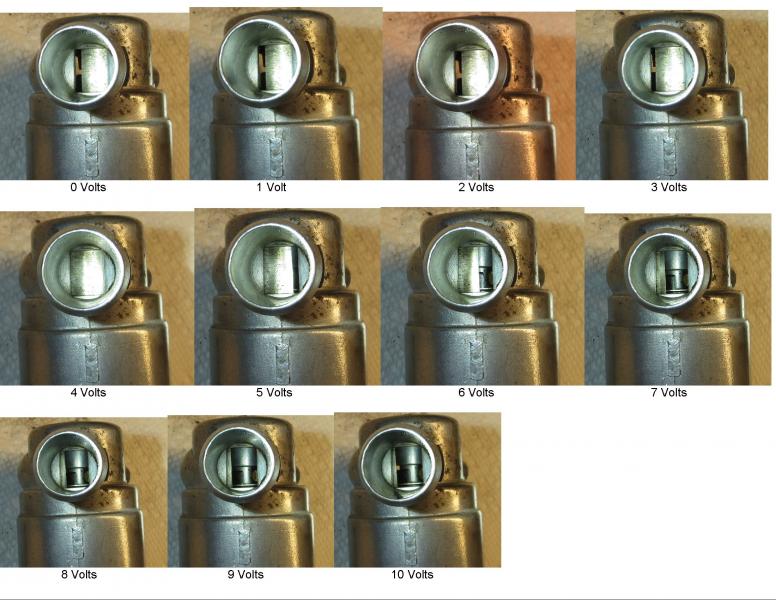
The Bosch idle valve is very common and is used on bmw's, volvo's etc.
Normally 120-200hz pwm is used. It is a spring loaded rotary valve.
I've used this valve with microsquirt and Haltech elite 750 and it works very well with those ecu's with virtually no tuning.
This picture shows it working with different voltages applied. Below 4v is a failsafe position and above 4v is where the air control is done.
-
gptech2444
- Posts: 46
- Joined: Mon Jan 22, 2018 9:01 pm
Re: IDLE not working
Ok, I didn't check duty with the oscilloscope and it would seem I would only get a change of idle speed when a whole percentage point change occured on the gauge.russian wrote: ↑Sat Jun 16, 2018 12:47 amidle output is a float value with a lot of precision, it's the gauge which had no decimal ponits - one digit after the point added.
period, verbose and offset clarification added - let me know if it's not exactly undestandable or maybe suggest some better wording if you see what I mean but you think it could be expressed better?
https://github.com/rusefi/rusefi/commit/2235d03e1fb646cebfdf7f29991eb6f20ad4c64b
Re: IDLE not working
I'm ignorant about your output. I recall the STM has a PWM output, which my faulty memory makes me believe you have a specific set of increments, then you set a clock to set the period, and have discrete number of output duty steps. This might not be the most optimal output, and may be limited in resolution.
Does this have some kind of feedback? AKA do you know if you have reached your target position? The idle valve is acting like a low pass filter. When you PWM the signal, it has an average signal which correlates to your 6 to 7V signal. Also it looks like 0V to 3V are actually open, but on the wrong side. That seems odd to me, but meh, you really open between 6 and 7V. Do you know what amps you have at 6V and at 7V?
This valve is mostly controlled via amps, not voltage. You really want an amps driver. However you can do an near equivalent with PWM, or some other pulse algo. The PWM add's an interesting feature as it does what's known as dithering. This dithering is handy as it prevents the valve from sticking and remove hysteresis issues. Do you know the inductance of this valve?
Welcome to the friendlier side of internet crazy
Re: IDLE not working
Having the valve slightly open at 0V could be a fail-safe. We get some basic idle, even if the valve-driver fails. If so, then I find the solution rather creative.
Re: IDLE not working
what exactly did you name creative?
I guess, this Bosch thing is used in my, my father's and my brother's audis
It has just two terminals, and no other direct feedback except these two wires. (indirect is probably through MAP sensors in electric systems and Idon'tknowwhat in k-jetronic CIS)
I guess, this Bosch thing is used in my, my father's and my brother's audis
It has just two terminals, and no other direct feedback except these two wires. (indirect is probably through MAP sensors in electric systems and Idon'tknowwhat in k-jetronic CIS)
-
Simon@FutureProof
- contributor

- Posts: 413
- Joined: Tue Jul 24, 2018 8:55 pm
- Github Username: Orchardperformance
- Slack: Orchardperformance
Re: IDLE not working
Something that might be worth mentioning here is that a lot of the cars that use that kind of idle valve have hybrid idle control strategies that use the valve for slow/course control of the idle speed and then use the ignition timing as a fast control.
The idle valve control is not fast enough to smooth out sub 1 second variations in the idle speed so it is only moved slowly from a fail safe position down to the minimum opening that is still above the requested idle speed then the timing is advanced or retarded to increase or decrease the power of the engine smoothing out the higher frequency fluctuations.
This might be something that is easier to setup than the PID for that kind of idle valve as you only need a slow PID for the valve and a small lookup table that can be adjusted to tune the advance/retard curve that will keep it at the desired RPM.
Now keeping MRE in stock in the UK - https://www.FutureProofPerformance.com