

And my new favorite chips are TLE8110EE (older version available on eBay, not recommended for new designs) and TLE8110ED (available on Moused, new product) - please help me by finding the differences between these two?
The datasheet clearly says "4 to 6 injectors", also this chip takes both +5 and +3.3 powers and officially allows 3.3v SPI.
Pretty please someone please help with a breakout board? Placing eBay order for TLE8110EE now.
Minimal wiring:
Vdd=5v
Vcc=3.3v
GND
EN,RST pulled up to VCC
[help needed] TLE8110 10 channel low side breakout board
-
AndreyB

- Site Admin
- Posts: 14323
- Joined: Wed Aug 28, 2013 1:28 am
- Location: Jersey City
- Github Username: rusefillc
- Slack: Andrey B

TLE8110 10 channel low side breakout board
Very limited telepathic abilities - please post logs & tunes where appropriate - http://rusefi.com/s/questions
Always looking for C/C++/Java/PHP developers! Please help us see https://rusefi.com/s/howtocontribute
Always looking for C/C++/Java/PHP developers! Please help us see https://rusefi.com/s/howtocontribute

Re: TLE8110 breakout board
I can take a stab at it, but it looks like this new Infineon package DG-PSO-36 is not available in the KICAD package repos. So I'll have to design it. It's been a while since I've done something like that.

Re: TLE8110 breakout board
KICAD 4.0.5 please. I plan to switch to KICAD 6 when that comes out. For now I'm stuck with KICAD 4 as I don't want to do the work to change the libs to KICAD 5. It looks like libs will need to be changed again in KICAD 6.
If you have trouble with the footprint and symbol, let me know. I have tomorrow off, then it's back to the salt mine on Wednesday.
If you have trouble with the footprint and symbol, let me know. I have tomorrow off, then it's back to the salt mine on Wednesday.
Welcome to the friendlier side of internet crazy 
Re: TLE8110 breakout board
- PG-DSO-36.png (154.69 KiB) Viewed 15230 times
Re: TLE8110 10 channel low side breakout board10
That should help- thanks!
@: Installing KiCAD 4.05 now.
For the breakout board: Do we want two rows of single pin headers for easy breadboard installation, or something more creative to minimize real estate needed?
@: Installing KiCAD 4.05 now.
For the breakout board: Do we want two rows of single pin headers for easy breadboard installation, or something more creative to minimize real estate needed?
-
AndreyB
- Site Admin
- Posts: 14323
- Joined: Wed Aug 28, 2013 1:28 am
- Location: Jersey City
- Github Username: rusefillc
- Slack: Andrey B
Re: TLE8110 10 channel low side breakout board10
We want output wire holes to be bigger like on https://github.com/rusefi/rusefi/tree/master/hardware/low_side_tle6240
I would say do not think about real estate too much at this point, extra $5 for oshpark would make little difference.
We also want holes under the heat dissipating belly of the chip like on https://github.com/rusefi/rusefi/tree/master/hardware/DDPAK_breakout - these are solderable holes so that I can fill it with paste or solder
Very limited telepathic abilities - please post logs & tunes where appropriate - http://rusefi.com/s/questions
Always looking for C/C++/Java/PHP developers! Please help us see https://rusefi.com/s/howtocontribute
Always looking for C/C++/Java/PHP developers! Please help us see https://rusefi.com/s/howtocontribute
Re: TLE8110 10 channel low side breakout board10
Yes- we definitely need the heat-conduction to the other side of the board. Shouldn't be a problem. Single row header pin can take up to 5A. That's plenty for injectors. Or is there another reason for bigger holes? Which ones on the tle6240 board are you referring to? Looks like we have at least 2 different hole sizes. I'll probably incorporate 4 GND pins, so we don' lose too much on the GND side of things.russian wrote: ↑Tue Jan 01, 2019 4:28 am[...]We want output wire holes to be bigger like on https://github.com/rusefi/rusefi/tree/master/hardware/low_side_tle6240 [...]
We also want holes under the heat dissipating belly of the chip like on https://github.com/rusefi/rusefi/tree/master/hardware/DDPAK_breakout - these are solderable holes so that I can fill it with paste or solder
-
AndreyB
- Site Admin
- Posts: 14323
- Joined: Wed Aug 28, 2013 1:28 am
- Location: Jersey City
- Github Username: rusefillc
- Slack: Andrey B
Re: TLE8110 10 channel low side breakout board10
size=1.8mm holes for outputs so that I can solder 20awg wires right to breakout board.
Very limited telepathic abilities - please post logs & tunes where appropriate - http://rusefi.com/s/questions
Always looking for C/C++/Java/PHP developers! Please help us see https://rusefi.com/s/howtocontribute
Always looking for C/C++/Java/PHP developers! Please help us see https://rusefi.com/s/howtocontribute
Re: TLE8110 10 channel low side breakout board10
russian wrote: ↑Tue Jan 01, 2019 1:37 amAnd my new favorite chips are TLE8110EE (older version available on eBay, not recommended for new designs) and TLE8110ED (available on Moused, new product) - please help me by finding the differences between these two?
The datasheet clearly says "4 to 6 injectors", also this chip takes both +5 and +3.3 powers and officially allows 3.3v SPI.
Pretty please someone please help with a breakout board? Placing eBay order for TLE8110EE now.
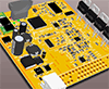
Infineon already have shield/Eval board for the 8110ED in Arduino standard.
I have used these for my design
https://www.infineon.com/cms/en/product/evaluation-boards/tle8110ed_dev_board/
- Attachments
-
- TLE8110ED.jpg (508.7 KiB) Viewed 15432 times
Re: TLE8110 10 channel low side breakout board10
Also olimex has a STM32 Arduino format board for low dollars. That 9V to 30V supply works good enough for prototypeing purposes.
https://www.olimex.com/Products/Duino/STM32/OLIMEXINO-STM32/open-source-hardware
https://www.olimex.com/Products/Duino/STM32/OLIMEXINO-STM32/open-source-hardware
Welcome to the friendlier side of internet crazy
Re: TLE8110 10 channel low side breakout board10
Even Infineon has a "arduino now"
Bit of a overkill
https://www.infineon.com/cms/en/product/evaluation-boards/kit_aurix_tc275_ard_sb/
Bit of a overkill
https://www.infineon.com/cms/en/product/evaluation-boards/kit_aurix_tc275_ard_sb/
-
AndreyB
- Site Admin
- Posts: 14323
- Joined: Wed Aug 28, 2013 1:28 am
- Location: Jersey City
- Github Username: rusefillc
- Slack: Andrey B
Re: TLE8110 10 channel low side breakout board10
Damn 
TLE8110ED - new version - is 0.5mm pitch, 10.3mm total - $8 from US
TLE8110EE - old version - is 0.65mm pitch, 12.8mm total - $2 from China
I really liked my idea to ignore the fact that these are different part numbers, now that @ has created https://github.com/rusefi/rusefi/tree/master/hardware/TLE8110ED_breakout_board it would be harder to ignore.
I will think about it tomorrow.
Very limited telepathic abilities - please post logs & tunes where appropriate - http://rusefi.com/s/questions
Always looking for C/C++/Java/PHP developers! Please help us see https://rusefi.com/s/howtocontribute
Always looking for C/C++/Java/PHP developers! Please help us see https://rusefi.com/s/howtocontribute

Re: TLE8110 10 channel low side breakout board10
The answer is blowin' in the wind? (с)
- TLE8110EE_NRND.jpg (78.71 KiB) Viewed 15225 times
-
AndreyB
- Site Admin
- Posts: 14323
- Joined: Wed Aug 28, 2013 1:28 am
- Location: Jersey City
- Github Username: rusefillc
- Slack: Andrey B
Re: TLE8110 10 channel low side breakout board10
Just placed an order with elecrow, $9.99 for red boards - I like that they allow color selection for no extra $.
Very limited telepathic abilities - please post logs & tunes where appropriate - http://rusefi.com/s/questions
Always looking for C/C++/Java/PHP developers! Please help us see https://rusefi.com/s/howtocontribute
Always looking for C/C++/Java/PHP developers! Please help us see https://rusefi.com/s/howtocontribute
Re: TLE8110 10 channel low side breakout board10
Except purple. Purple is a bunch more, maybe because they're stepping on oshpark's turf?
-
AndreyB
- Site Admin
- Posts: 14323
- Joined: Wed Aug 28, 2013 1:28 am
- Location: Jersey City
- Github Username: rusefillc
- Slack: Andrey B
Re: TLE8110 10 channel low side breakout board10
Got 10 boards yesterday, so it was 17 days. Now need to order the chip...
Very limited telepathic abilities - please post logs & tunes where appropriate - http://rusefi.com/s/questions
Always looking for C/C++/Java/PHP developers! Please help us see https://rusefi.com/s/howtocontribute
Always looking for C/C++/Java/PHP developers! Please help us see https://rusefi.com/s/howtocontribute
-
AndreyB
- Site Admin
- Posts: 14323
- Joined: Wed Aug 28, 2013 1:28 am
- Location: Jersey City
- Github Username: rusefillc
- Slack: Andrey B
Re: TLE8110 10 channel low side breakout board10
We got it soldered!
Need a couple of changes to make future revision easier to work with - as is it's harder than it should be.
Should we connect grounds right on the board? At the moment six GND traces just to the header separately.
We also had some fun distinguishing index mark deep circle from ejector shallow circle. Did not realize there is another index mark on the rear side of the chip!
Next step would be to click some injectors1) set solder mask to 0.003 inches, per OSHPark suggestion.
2) make footprint pads longer so that we have some metal not covered by the chip
- Attachments
-
- fun_marking.png (67.13 KiB) Viewed 14985 times
-
- tle8110ed_board.jpg (538.09 KiB) Viewed 14985 times
Very limited telepathic abilities - please post logs & tunes where appropriate - http://rusefi.com/s/questions
Always looking for C/C++/Java/PHP developers! Please help us see https://rusefi.com/s/howtocontribute
Always looking for C/C++/Java/PHP developers! Please help us see https://rusefi.com/s/howtocontribute
-
AndreyB
- Site Admin
- Posts: 14323
- Joined: Wed Aug 28, 2013 1:28 am
- Location: Jersey City
- Github Username: rusefillc
- Slack: Andrey B
Re: TLE8110 10 channel low side breakout board10
The board works! I have an injector clicking as I type this.
3) since RST is not needed, connect with Pull-up resistor to VCC
4) since EN is not needed, connect with Pull-up resistor to VCC
5) it is highly recommended to connect the exposed pad to GND pins on the PCB.
Very limited telepathic abilities - please post logs & tunes where appropriate - http://rusefi.com/s/questions
Always looking for C/C++/Java/PHP developers! Please help us see https://rusefi.com/s/howtocontribute
Always looking for C/C++/Java/PHP developers! Please help us see https://rusefi.com/s/howtocontribute
-
AndreyB
- Site Admin
- Posts: 14323
- Joined: Wed Aug 28, 2013 1:28 am
- Location: Jersey City
- Github Username: rusefillc
- Slack: Andrey B
Re: TLE8110 10 channel low side breakout board10
Since I am playing with random injectors, is there such a thing as standard injector polarity? Is the left pin with output side up always positive?
- Attachments
-
- Fuel Injector.jpg (37.76 KiB) Viewed 14968 times
Very limited telepathic abilities - please post logs & tunes where appropriate - http://rusefi.com/s/questions
Always looking for C/C++/Java/PHP developers! Please help us see https://rusefi.com/s/howtocontribute
Always looking for C/C++/Java/PHP developers! Please help us see https://rusefi.com/s/howtocontribute
Re: TLE8110 10 channel low side breakout board10
I have not heard of such a thing, it would be interesting to learn if such a think exists. I could think of some tests if you wanted to try to test things out.
Welcome to the friendlier side of internet crazy
Re: TLE8110 10 channel low side breakout board10
Do injectors even have a polarity? I always thought they would fire no matter the direction of the current...
-
AndreyB
- Site Admin
- Posts: 14323
- Joined: Wed Aug 28, 2013 1:28 am
- Location: Jersey City
- Github Username: rusefillc
- Slack: Andrey B
Re: TLE8110 10 channel low side breakout board10
Injector is a solenoid https://en.wikipedia.org/wiki/Solenoid which is an electromagnet - so with wrong polarity it would want to close more instead of opening I guess?
Very limited telepathic abilities - please post logs & tunes where appropriate - http://rusefi.com/s/questions
Always looking for C/C++/Java/PHP developers! Please help us see https://rusefi.com/s/howtocontribute
Always looking for C/C++/Java/PHP developers! Please help us see https://rusefi.com/s/howtocontribute
Re: TLE8110 10 channel low side breakout board10
It does make sense to inquire. Solenoids (sol) commonly do have a polarity requirement, and an injector is a type of sol. Some sol's simply have a piece of metal which is pulled by a magnet, and this does not matter about polarity. Other have a magnet or similar embedded in the moving part, such that they require less energy to activate etc. The N and S poles will either pull or push, so really obvious if wired backwards. It is also common for industrial sol's to be a DC sol, with internal diodes which rectify the signal to get the proper polarity. Such that they can be AC or DC sol's. These often cost more, as they are more than just a pile of wire. As well if you wire it one way, you have diode drops, and the other way there are no diode drops, so it's faster acting.
Any how, in terms of injectors, there are many potential concerns, ranging from the hysteresis of the pintle metal, to internal BEMF. You might have a different charging curve if you flip the wires. This would potentially change your delivered fuel. I really don't know how much that could effect things, but it's something to consider.
Any how, in terms of injectors, there are many potential concerns, ranging from the hysteresis of the pintle metal, to internal BEMF. You might have a different charging curve if you flip the wires. This would potentially change your delivered fuel. I really don't know how much that could effect things, but it's something to consider.
Welcome to the friendlier side of internet crazy
-
AndreyB
- Site Admin
- Posts: 14323
- Joined: Wed Aug 28, 2013 1:28 am
- Location: Jersey City
- Github Username: rusefillc
- Slack: Andrey B
Re: TLE8110 10 channel low side breakout board
90 minutes IR test with 5 injectors (with board hard to solder and OUT6 trace going under the chip not away from the chip looks like OUT6 is not happy on this board)
This is all testing I plan for this board at this point. Do not plan to play with SPI at least in the immediate future, maybe I should. I think we can make rev 0.2 since no more feedback would probably arrive any day soon.
This is all testing I plan for this board at this point. Do not plan to play with SPI at least in the immediate future, maybe I should. I think we can make rev 0.2 since no more feedback would probably arrive any day soon.
Very limited telepathic abilities - please post logs & tunes where appropriate - http://rusefi.com/s/questions
Always looking for C/C++/Java/PHP developers! Please help us see https://rusefi.com/s/howtocontribute
Always looking for C/C++/Java/PHP developers! Please help us see https://rusefi.com/s/howtocontribute

Re: TLE8110 10 channel low side breakout board
As for the polarity of the injectors - I have never conducted an experience, but I collected more than one wiring from scratch, there were many of them. Where I did not observe the polarity, but always plus power and the ground on all the injectors was the same. On some circuits I met the labeling of the injectors as 1 and 2 only on circuit diagrams and not when on connectors. By experience, I can say that it doesn’t matter how to turn on the injector, the main rule is to connect all the injectors identically.
Re: TLE8110 10 channel low side breakout board
Some comments, if you do a time lapse, we can detect if the the injectors and PCB have reached steady state. Basically when the pictures stop changing temperature, then we can compare the hot spot, to the ambient. Once we know the temperature difference, we can calculate the thermal resistance. Once we know the existing thermal resistance, we could make predictions on how much smaller we can safely trim the board, or we could determine if the temperature rise at the max ambient temperature would be acceptable.
Any how, good to see my Flir One Gen2 is getting some good use.
Also I don't think we need to predict the board size, we can simply trim the board. However with the camera, we could predict how much we can trim the board down, but we don't need to.
Any how, good to see my Flir One Gen2 is getting some good use.
Also I don't think we need to predict the board size, we can simply trim the board. However with the camera, we could predict how much we can trim the board down, but we don't need to.
Welcome to the friendlier side of internet crazy
Re: TLE8110 10 channel low side breakout board
I also seem to recall you can touch the screen in several places and take several readings at the same time. So you could potentially measure all injectors and the PCB in one view. Then do the time lapse.
Welcome to the friendlier side of internet crazy
-
AndreyB
- Site Admin
- Posts: 14323
- Joined: Wed Aug 28, 2013 1:28 am
- Location: Jersey City
- Github Username: rusefillc
- Slack: Andrey B
Re: TLE8110 10 channel low side breakout board
Just moved this board to https://github.com/rusefi/hw_modular
List of current wishes is at https://github.com/rusefi/hw_modular/blob/master/TLE8110ED_breakout_board/known_issues.txt - it's about known issues and transitioning to the Manhattan double-row approach. See attached napkin dream.
List of current wishes is at https://github.com/rusefi/hw_modular/blob/master/TLE8110ED_breakout_board/known_issues.txt - it's about known issues and transitioning to the Manhattan double-row approach. See attached napkin dream.
- Attachments
-
- napkin_wishes_for_0_2.jpg (227.96 KiB) Viewed 14612 times
Very limited telepathic abilities - please post logs & tunes where appropriate - http://rusefi.com/s/questions
Always looking for C/C++/Java/PHP developers! Please help us see https://rusefi.com/s/howtocontribute
Always looking for C/C++/Java/PHP developers! Please help us see https://rusefi.com/s/howtocontribute