Page 3 of 3
Re: Sprut - A newbies try to design an ECU
Posted: Tue Nov 12, 2019 2:21 pm
by InternetAthiest
Sorry for not responding during the weekend, but I'll try to answer everything.
DonaldBecker wrote: ↑Fri Nov 08, 2019 4:23 pm
In boot1 update mode pins related to the active interfaces will switch from floating to being actively driven. It's a good way to verify that the processor is working, especially comparing to reset into normal mode.
Really wierd that it does not drive them, might be two bad MCUs then. Also, where does it say that it drives the active interfaces in boot mode?
JRD McLAREN wrote: ↑Fri Nov 08, 2019 6:05 pm
..try to disconnect RESET pin after power-up .. ..
Do you mean all of the components connecting to reset? The pins are push buttons so I'm certain that reset is disconnected and pulled high otherwise.
mck1117 wrote: ↑Mon Nov 11, 2019 11:31 pm
Do you have SWD wired? If so you can attach a debugger and see what it's doing (or not doing).
Unfortunetly I do not have SWD wired nor do I have any form of st-link, j-link or jtag interface/adapter. But it's on the list of things to get!
I've been using the ftdi chip on an Arduino Uno as the uart adapter with the atmega mcu being in constant reset state as to not interfere with communication. It has built in pull-ups on the data lines at about 50k ohm each. But I cannot see why this would be the problem as I've communicated and flashed other uart things with this method and it works fine. I'm really starting to question the MCU and the components surrounding it. Might just build one sprut with only the parts needed to get a running MCU.
Re: Sprut - A newbies try to design an ECU
Posted: Tue Nov 12, 2019 2:55 pm
by AndreyB
st-link devices start at $4 on eBay and discovery board with st-link on it is $20
you seem to be operating with too many artificial constraints in my opinion
Re: Sprut - A newbies try to design an ECU
Posted: Tue Nov 12, 2019 4:45 pm
by DonaldBecker
russian wrote: ↑Tue Nov 12, 2019 2:55 pm
st-link devices start at $4 on eBay and discovery board with st-link on it is $20
You might spend $4 if you are a bad shopper. I paid less than that for one in early 2015. I'm seeing them under $2 on FleaBay, shipping included.
And every STM32 discovery board has an embedded ST-Link that can be jumpered to program external boards. The discovery boards used to cost less than the retail price of the processors on them.
The debugging and trace capability built into the STM32 (and ARM Cortex-M in general) is amazing, especially if you grew up when a debugging module cost thousands of dollars.
Re: Sprut - A newbies try to design an ECU
Posted: Tue Nov 19, 2019 12:52 am
by InternetAthiest
After reading about 20 different manuals and papers from ST I think I might have found the problem. Apparently I misunderstood that VCAP_1 and VCAP_2 should have just ONE 2.2uF capacitor each instead of two. I've not tested this yet but hopefully it will solve the issue.
Re: Sprut - A newbies try to design an ECU
Posted: Wed Nov 20, 2019 12:29 am
by 960
I have a test-adapter/socket for stm32 144-pin.
I dont need one single cap or resistor to flash firmware (SWD or DFU), and communicate over both uart and native USB.
The only component I have are a 8 mhz crystal, nothing else..
Re: Sprut - A newbies try to design an ECU
Posted: Wed Nov 20, 2019 12:39 am
by AndreyB
960 wrote: ↑Wed Nov 20, 2019 12:29 am
I have a test-adapter/socket for stm32 144-pin.
The only component I have are a 8 mhz crystal, nothing else..
A picture would be interesting!
Re: Sprut - A newbies try to design an ECU
Posted: Wed Nov 20, 2019 1:29 am
by 960
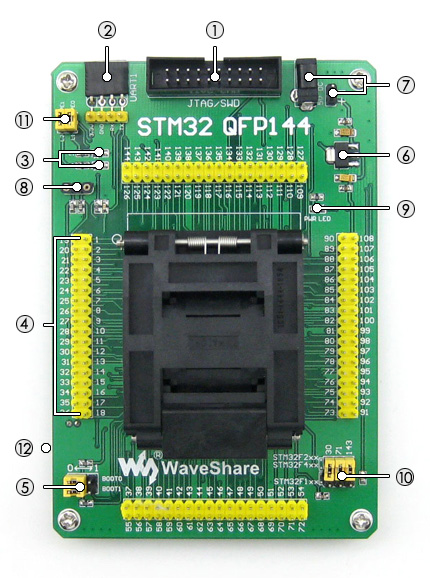
- STM32-QFP144-intro.jpg (149.83 KiB) Viewed 12888 times
https://www.waveshare.com/product/mcu-tools/stm32/adapters/stm32-qfp144.htm
They have for the whole range 48 Pin to 176 Pin.
I have it running firmware with only a crystal in the socket 8.
Re: Sprut - A newbies try to design an ECU
Posted: Wed Nov 20, 2019 1:38 am
by 960
So even if you strip your whole pcb to only the mcu, 3.3V and a crystal, it should run
Re: Sprut - A newbies try to design an ECU
Posted: Thu Nov 28, 2019 7:37 pm
by Ahmad
960 wrote: ↑Wed Nov 20, 2019 1:38 am
So even if you strip your whole pcb to only the mcu, 3.3V and a crystal, it should run
Decoupling capacitors may be placed under MCU socket!
Re: Sprut - A newbies try to design an ECU
Posted: Fri Nov 29, 2019 4:46 pm
by 960
Ahmad wrote: ↑Thu Nov 28, 2019 7:37 pm
960 wrote: ↑Wed Nov 20, 2019 1:38 am
So even if you strip your whole pcb to only the mcu, 3.3V and a crystal, it should run
Decoupling capacitors may be placed under MCU socket!
Nothing..
https://www.waveshare.com/w/upload/9/99/STM32-QFP144-Schematic.pdf
Re: Sprut - A newbies try to design an ECU
Posted: Sat Nov 30, 2019 12:54 am
by NickZ
Do you know, the first one i did, i put the processor on the wrong way thinking the writing on the chip would start the first letter at pin one, WRONG!

- 20191130_110508.jpg (1.24 MiB) Viewed 12783 times

- 20191130_110515.jpg (653.45 KiB) Viewed 12783 times
But this is all I need to fire up the processor and flash the firmware, but i am using a ST-Link V2.
Re: Sprut - A newbies try to design an ECU
Posted: Sat Nov 30, 2019 6:36 am
by puff
so you fried it? or it survived ?
Re: Sprut - A newbies try to design an ECU
Posted: Sat Nov 30, 2019 11:05 am
by NickZ
blew a hole in it
