Page 1 of 8
Wideband Controller: Fully Custom, no ASIC!
Posted: Fri Oct 30, 2020 1:41 am
by mck1117
I've started work on building a wideband controller from scratch, using no hard to source ASICs, like the Bosch CJ125 family.
Goals:
- Use only widely available, easy to source components. Right now the design has nothing more interesting than a general purpose microcontroller (STM32F042 LQFP-32), general purpose opamps, a low side driver, and passives.
- Support Bosch LSU 4.9 sensor. The LSU 4.2 requires free air calibration, and 4.9 sensors are so widespread that there's not a good reason to support the older sensors.
- Support both in-ECU use, as well as standalone. That means SPI or serial comms with an ECU, and CAN or analog for external use.
The GitHub repository for both hardware and firmware is here:
https://github.com/mck1117/wideband/
Here's the module as it exists today:

- image.png (461.13 KiB) Viewed 154985 times
The SD-card-sized module can run either inside an ECU, or independently when stacked on the board with the big connector. The second board just provides a power supply and CAN interface, parts that are unnecessary when inside an ECU. Everything required to run the sensor is on the tiny module.
NOT STANDALONE: REQUIRES VOLTAGE DATA INPUT VIA CAN as provided by primary rusEFI standalone firmware
Re: Wideband Controller: Fully Custom, no ASIC!
Posted: Fri Oct 30, 2020 2:10 am
by mck1117
Ok, so how do these wideband sensor things work anyway?
Let's start with a narrowband sensor. All a narrowband sensor does is determine whether its surrounding environment is oxidising (lean) or reducing (rich).

- image.png (98.12 KiB) Viewed 157367 times
This isn't very useful if we want any information other than whether the engine is very close to stoichiometric.
A wideband sensor adds a second cell, similar to the first, except that this one is driven instead of measured.

- image.png (36.05 KiB) Viewed 157367 times
The pump cell biases the "stoichiometric point" of the measurement cell. By driving current in or out of the pump cell such that the measurement cell's voltage is ~0.45 volt, we can determine the true lambda based on how much pump current was required to do so:
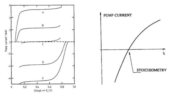
- image.png (87.42 KiB) Viewed 157367 times
However, this chemistry is only accurate at a particular temperature. The measurement Nernst cell isn't a perfect voltage source though: it has an internal resistance, and that internal resistance varies with the temperature. The internal resistance is continuously measured with an injected AC current, the result of which is used to control the heater integral to the sensor.
Attached to this post is a great masters thesis pdf by Damien Chazal that details the chemistry and electronics behind how wideband O2 sensors operate.
Re: Wideband Controller: Fully Custom, no ASIC!
Posted: Fri Oct 30, 2020 2:46 am
by mck1117
Ok, time for hardware testing. First step is to validate that the hardware does what I think it does, before even connecting a sensor.
Pump Current Source
Expected function: PWM is generated by the microcontroller, converted to analog, and sets the output current from -5.2mA to +5.2mA.
U1A uses R8 as a sense resistor, and combined with the gain, that gives the output range (note: the output range can be limited if the opamp output hits the rails).
Test setup: A 100 ohm resistor was installed between LSU_Ip and LSU_Vm, simulating the sensor's pump cell. Multimeter measuring the voltage drop across the resistor to measure current. Current target stepped from -5mA to +5mA, output voltage recorded.
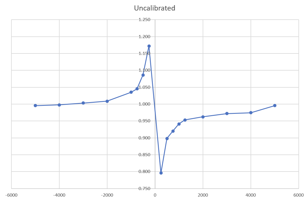
- image.png (33.25 KiB) Viewed 157363 times
Well that's...not ideal. That should be a flat 1.0 all the way across, indicating that the output current is exactly what we wanted. A shape like that indicates that there's a fixed-ish offset away from zero, which is confirmed by the data. There's an average offset of around 42 microamps, most likely from the input offset voltage on the opamp. We could calibrate out that offset in software, but the offset could drift with age and temperature. As a test, I tried offsetting the target by 42uv to see what happens:
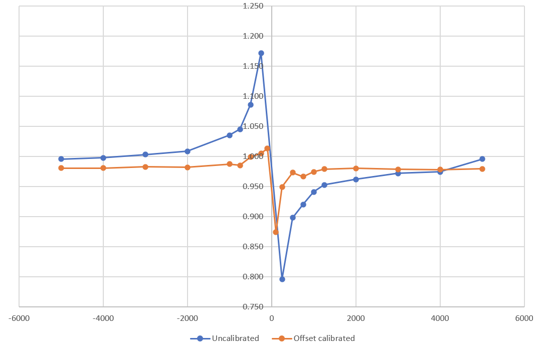
- image.png (38.68 KiB) Viewed 157363 times
Hey, that looks better! Still some error very close to 0 current, but that's pretty much unavoidable without extreme measures. Better opamps would definitely help.
Takeaways:
- Pump current driver works as expected
- Better opamps may be required if the offset ends up being a problem. TBD whether it's an issue when driving a real sensor. The current opamps are MCP6004, which has a rated input offset voltage of up to +-4.5mV, which is pretty enormous as far as opamp input offsets go. Chopper stabilized opamps can pretty easily get down below 10uV input offset, an order of magnitude better (and are very temperature stable).
Re: Wideband Controller: Fully Custom, no ASIC!
Posted: Fri Oct 30, 2020 4:33 pm
by Joey120373
looks very interesting! good work. Have you thought about using chopper type op-amps to reduce the op-amp input bias?
Re: Wideband Controller: Fully Custom, no ASIC!
Posted: Fri Oct 30, 2020 5:39 pm
by kb1gtt
Looks like allot of the schematic is very similar to this one Waltech did, except STM32 instead of AVR. Good to see a more useful version of the design being done.
https://waltech.com/cszcms/wide-band-oxygen-sensor-project-report
Once a standalone board is done, could this be merged native rusEFI firmware(s)?
Re: Wideband Controller: Fully Custom, no ASIC!
Posted: Fri Oct 30, 2020 6:06 pm
by mck1117
Joey120373 wrote: ↑Fri Oct 30, 2020 4:33 pm
looks very interesting! good work. Have you thought about using chopper type op-amps to reduce the op-amp input bias?
Yes, that is an option. The trouble is that they're generally not very cheap... The MCP6004 (as installed by JLCPCB) is only 30 cents each. They carry the ADA4522 in the same package (the gold standard of low offset and low noise), but they're $11 each! A chopper amp isn't necessarily required, there are plenty of normal cmos opamps that aren't as bad as the mcp6004 (a quick survey indicates that the mcp6004 is just about as bad as it can get).
Re: Wideband Controller: Fully Custom, no ASIC!
Posted: Fri Oct 30, 2020 6:11 pm
by mck1117
Yes - inspiration was definitely drawn from there. There are a handfull of improvements though, particularly that the pump driver is a current source, not just a voltage supply.
kb1gtt wrote: ↑Fri Oct 30, 2020 5:39 pm
Once a standalone board is done, could this be merged native rusEFI firmware(s)?
Mayyyybe. It's probably not worth running on the main processor, since it needs sort of precise timing, and exclusive use of the ADC channels involved (it's sampling at ~5khz). Also there's really not a cost concern, since the STM32F042K6 MCU on here is literally $1 in quantity from JLC:

- image.png (39.27 KiB) Viewed 157211 times
Re: Wideband Controller: Fully Custom, no ASIC!
Posted: Fri Oct 30, 2020 8:32 pm
by mck1117
Next step:
Pump Current Sense
The pump current flows to the sensor through two parallel resistors: a 61.9 ohm resistor on the board, and a 30-300 trim resistor in the sensor connector. The trim resistor is calibrated at the factory so that the voltage drop across the sense resistors (between LSU_Ip and LSU_Rtrim) matches the specified "nominal current" (aka voltage drop across a 61.9 ohm resistor) and actual lambda.
Expected behavior: a 10x gain of the voltage across the sense resistor, offset by the 1.65v virtual ground. Current was swept from -2.5 to +2.5 mA (with the offset correction from the previous section), and the output of the current sensing logged.

- image.png (31.49 KiB) Viewed 157203 times
Looks pretty good to me. There's a little bit of offset in the result, but it's not bad at all. The gain error makes it look worse than it is in the middle (if you had 5uA target, 10uA actual = 2x gain!), so it might be better to look at the absolute error, not the ratio. The error is well under 15uA across the whole range!
Notice that because this test was completely automated (self contained on the mcu), there are many more data points than the previous test.
Re: Wideband Controller: Fully Custom, no ASIC!
Posted: Sat Oct 31, 2020 12:33 pm
by AndreyB
At the moment that's a $8 with quantity 10 mostly assembled PCB which requires a $3.5 FTSH-107-01-F-DV-K connector?
https://github.com/mck1117/wideband/issues/1 created
But OMG, that's a $12 wideband controller!!!
Re: Wideband Controller: Fully Custom, no ASIC!
Posted: Sat Oct 31, 2020 2:33 pm
by mk e
Cylinder O2 readings for everyone!
Re: Wideband Controller: Fully Custom, no ASIC!
Posted: Sun Nov 01, 2020 5:21 pm
by deezums
Would it be possible to add support for the LSU-ADV sensor? It doesn't use a calibration resistor, so adapting it to a custom harness with this built into the ECU would be one step easier, right? I'm not sure what the difference on the board would need to be, could we populate a jumper for a 4.2/4.9 and a built in cal resistor for the ADV?
Edit: Actually looks like you could just add a resistor and only populate it if you plan on using an ADV sensor? Maybe no resistor at all?
I have some spare 4.9 sensors and bungs in my exhaust and was about to place an order for some PCBs. Would logs compared to a 14point7 S3 ADV be helpful in any way?
Re: Wideband Controller: Fully Custom, no ASIC!
Posted: Sun Nov 01, 2020 9:16 pm
by mck1117
deezums wrote: ↑Sun Nov 01, 2020 5:21 pm
Would it be possible to add support for the LSU-ADV sensor? It doesn't use a calibration resistor, so adapting it to a custom harness with this built into the ECU would be one step easier, right? I'm not sure what the difference on the board would need to be, could we populate a jumper for a 4.2/4.9 and a built in cal resistor for the ADV?
Edit: Actually looks like you could just add a resistor and only populate it if you plan on using an ADV sensor? Maybe no resistor at all?
Iirc the only difference is the AC nernst ESR measurement current, and pump current to lambda relationship. The former can be changed by swapping out a single resistor, and the latter is just software. The missing pin isn't a problem, just don't connect it. The signal is still there, it just stays inside the controller instead of also going to the sensor connector.
The other option is to duplicate the AC generation circuit (it's just a series RC, after all), and select which one to use based on the sensor type. Leaving the MCU pin as a floating input would effectively disconnect the unused one from the system.
deezums wrote: ↑Sun Nov 01, 2020 5:21 pm
I have some spare 4.9 sensors and bungs in my exhaust and was about to place an order for some PCBs. Would logs compared to a 14point7 S3 ADV be helpful in any way?
Probably not necessary yet - I have a second bung on my exhaust already too, and was about to make exactly that comparison.
Re: Wideband Controller: Fully Custom, no ASIC!
Posted: Sun Nov 01, 2020 10:30 pm
by mk e
Any idea when it might be ready for the general public?
Re: Wideband Controller: Fully Custom, no ASIC!
Posted: Sat Nov 14, 2020 8:48 am
by Gepro
Really nice !!!
But I understand anything

The WB 4.9 has 5 or 6 wires, the 6th is a resistance for calibration, don't always here, because of the same value on 4.9.
And in the 5, there is 2 for the heater, one for +12v, and one for GND.
On your schematics, I don't see +12v, so I believe it must come from another wire. But, why do you have so much wires on the J6 ?
Sorry, my electronic level is zero, and I don't understand how to plug it.
If I take your PCB and put a STM32F030C8T6 with 4 MCP6002 instead of 2 MCP6004, does it work ? I believe there is the room.
It just a question of cost efficiency, this is basic parts on JLC.
In fact, I would also put 5v regulator and canbus ship, in order to go full standalone, though canbus, SPI has too much wire.
I already have a wideband controller with a 4.2. On my other car, I plan to put it for tuning, and go for a narrowband once the tune done.
With your controller, I can go with a wideband everywhere.
Sorry for all my question and...
Thanks a lot for all your great work !!!
Re: Wideband Controller: Fully Custom, no ASIC!
Posted: Sat Nov 14, 2020 9:04 am
by mck1117
Gepro wrote: ↑Sat Nov 14, 2020 8:48 am
The WB 4.9 has 5 or 6 wires, the 6th is a resistance for calibration, don't always here, because of the same value on 4.9.
And in the 5, there is 2 for the heater, one for +12v, and one for GND.
On your schematics, I don't see +12v, so I believe it must come from another wire. But, why do you have so much wires on the J6 ?
Sorry, my electronic level is zero, and I don't understand how to plug it.
The 6 wires of the sensor are really 4+2 - 4 for the sensor, and 2 for the heater. The sensing pins connect directly. Heater- goes to the switched heater pin on the board, and heater+ goes directly to 12v.
Gepro wrote: ↑Sat Nov 14, 2020 8:48 am
If I take your PCB and put a STM32F030C8T6 with 4 MCP6002 instead of 2 MCP6004, does it work ? I believe there is the room.
It just a question of cost efficiency, this is basic parts on JLC.
In fact, I would also put 5v regulator and canbus ship, in order to go full standalone, though canbus, SPI has too much wire.
I already have a wideband controller with a 4.2. On my other car, I plan to put it for tuning, and go for a narrowband once the tune done.
With your controller, I can go with a wideband everywhere.
There is still very much a v1 board - there's a new revision in the works, probably ordered soon. It switches to use 1x MCP6004 + 1x AD8628 instead of the pair of MCP6004. And yes, that improvement really is important: it reduces the error in the pump current measurement to nearly zero, which in turn reduces the error in the measured lambda. I'm also going to do a "carrier board" that adds a 5v regulator, can transceiver, and connector.
I'm planning on running a batch of those (10ish perhaps?) to send to others to beta test, and I'm happy to send you one at cost if you're interested. Where are you located?
Re: Wideband Controller: Fully Custom, no ASIC!
Posted: Sat Nov 14, 2020 9:37 am
by mck1117
Gepro wrote: ↑Sat Nov 14, 2020 8:48 am
put a STM32F030C8T6
also the f030 doesn't have CAN at all
Re: Wideband Controller: Fully Custom, no ASIC!
Posted: Sat Nov 14, 2020 10:07 am
by Gepro
It will be a great pleasure to be a beta tester, I know it isn't free

I am in France, but you can send in a letter, no ?
I haven't LSU 4.9 for now, but I will. I don't know if I will give report rapidly.
Sorry, I don't look at the datasheet
And I always look for cost effiency for 2 or 5 boards, that don't make sense for 10.
Thanks,
Re: Wideband Controller: Fully Custom, no ASIC!
Posted: Mon Nov 16, 2020 11:29 pm
by Joey120373
more than happy to be a beta tester, live in the USA, working on a 1000cc vtwin at the moment.
Already have a WB02 installed.
Re: Wideband Controller: Fully Custom, no ASIC!
Posted: Wed Dec 16, 2020 1:48 am
by mck1117
Ok, time for updates! After some basic testing (idling in the driveway) of the first revision of the board, I ordered a batch of a second revision with some modifications to make it a small module instead of a development board:

- image.png (3.12 MiB) Viewed 156327 times
left: USB programming adapter center: wideband controller module right: module installed on its carrier board
The carrier board has a 12-pin sealed connector, protected 5v regulator, and CAN interface chip.
Here's a snip of a log from the very first drive:

- image.png (521.8 KiB) Viewed 156327 times
Channel "Lambda" (red) is an AEM X-Series inline controller, sniffing the right hand bank of the engine (even number cylinders).
Channel "Lambda 2" (green) is the new custom controller, sniffing the left hand bank of the engine (odd number cylinders).
The engine itself is a GM LS 5.3 liter V8. The Bosch sensors themselves are identical - but I don't expect the two banks of the engine to be perfectly identical. But they are always within a few percent, which is reflected by the log.
It certainly works! The PID loops for the pump control and heater both need some tuning (less bandwidth, mostly), and the output needs some better filtering. but it's a very promising start.
Tune and log are uploaded
here and
here.
Re: Wideband Controller: Fully Custom, no ASIC!
Posted: Fri Dec 18, 2020 11:25 pm
by Lambo97
Looking good, looks like that connector can be integrated into a 3d printed case. I'll spin up a Proteus V4 case with 2 slots for dual band once you get closer. Matt do you have any V4 boards left I'll send you the cash now to hold one for me.
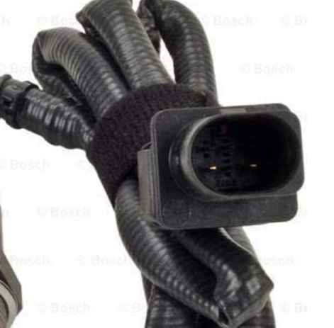
And to confirm this is the type of connector you are using for the LSU 4.9 ?

- image.png (259.19 KiB) Viewed 156257 times
Re: Wideband Controller: Fully Custom, no ASIC!
Posted: Sat Dec 19, 2020 12:09 am
by mck1117
Lambo97 wrote: ↑Fri Dec 18, 2020 11:25 pm
Looking good, looks like that connector can be integrated into a 3d printed case. I'll spin up a Proteus V4 case with 2 slots for dual band once you get closer.
Good idea - I've already printed a case for mine, so I can share the dimensions for the connector slot. It took a few tries to get the fit snug but not impossible to get it back out.

- image.png (5.32 MiB) Viewed 156253 times
Lambo97 wrote: ↑Fri Dec 18, 2020 11:25 pm
And to confirm this is the type of connector you are using for the LSU 4.9 ?
I think that's right, yes. The mating connector is available un-crimped (or you can harvest it from a junkyard car):
https://www.amazon.com/AEM-35-2617-Wideband-Connector-Digital/dp/B00ODRG93S/
Re: Wideband Controller: Fully Custom, no ASIC!
Posted: Mon Dec 21, 2020 11:52 pm
by Lambo97
Hey there, ok a little confused the connector on the Bosch LSU 4.9 17025 is a male plug the plug on your wideband board is male do i need to make a double ended female cable to connect the 2?
- image.png (309.93 KiB) Viewed 156162 times

- image.png (404.08 KiB) Viewed 156162 times
Re: Wideband Controller: Fully Custom, no ASIC!
Posted: Mon Dec 21, 2020 11:57 pm
by AndreyB
the carrier board has a 12-pin sealed connector
12 pin connector on the WBO is a totally different connector
12 pin connector connects not only the sensor but I assume also power supply for controller and CAN communication lines for WBO to talk to ECU?
Re: Wideband Controller: Fully Custom, no ASIC!
Posted: Tue Dec 22, 2020 12:41 am
by mck1117
Yep, Andrey has it right.
The 12 pin connector contains:
2x power
2x CAN bus
6x wideband
In fact, the back of the controller board has its own documentation about which pin is which:

- image.png (4.36 MiB) Viewed 156157 times
Re: Wideband Controller: Fully Custom, no ASIC!
Posted: Tue Dec 22, 2020 12:43 am
by mck1117
BTW for the beta batch I'm sending the mating plug for the controller (and crimp pins to go along), but not the LSU connector, but those are easy to snip off of a junkyard harness.
Re: Wideband Controller: Fully Custom, no ASIC!
Posted: Thu Dec 24, 2020 10:59 pm
by SHOf429
How do I sign up for the goodness? I'd like to run 2 of these on my V6
Re: Wideband Controller: Fully Custom, no ASIC!
Posted: Thu Dec 31, 2020 3:12 pm
by wstefan20
mck1117 nice work man! I'm thinking about adding this board jumpered onboard my 5.0 mustang proteus if that's ok? Since it's still in dev I figured it's probably best to do a jumper rather than directly print your schematic on my board since it could change. My experience with wideband O2 is limited but I'd be happy to help at least provide another test mule if you're cool with that?
Re: Wideband Controller: Fully Custom, no ASIC!
Posted: Thu Dec 31, 2020 4:07 pm
by Lambo97
mck1117 wrote: ↑Tue Dec 22, 2020 12:43 am
BTW for the beta batch I'm sending the mating plug for the controller (and crimp pins to go along), but not the LSU connector, but those are easy to snip off of a junkyard harness.
Just to confirm, are we OK with Chinese 17025 LSU4.9 O2 Wideband Bosch O2s that are all over ebay? or should we go factory OE Bosch? I'm not sure if there will be much of a difference except for cost is double.
Re: Wideband Controller: Fully Custom, no ASIC!
Posted: Thu Dec 31, 2020 5:15 pm
by SHOf429
Is there a possibility of making this a dual channel device? Duplicate the input stage, use some of the unused pins of the STM and feed the output of both channels to the mcu? With the CAN protocol, each sensor can have a different output ID. Either interface for that matter. I like the idea of it being a standalone device connected to the MCU via CAN. Feed that same data to a gauge...
Re: Wideband Controller: Fully Custom, no ASIC!
Posted: Thu Dec 31, 2020 11:15 pm
by mck1117
SHOf429 wrote: ↑Thu Dec 31, 2020 5:15 pm
Is there a possibility of making this a dual channel device? Duplicate the input stage, use some of the unused pins of the STM and feed the output of both channels to the mcu? With the CAN protocol, each sensor can have a different output ID. Either interface for that matter. I like the idea of it being a standalone device connected to the MCU via CAN. Feed that same data to a gauge...
The MCU is currently limited on the sample rate of the ADC. It can't really sample more at the same time without reducing accuracy or going to a faster MCU with multiple ADCs. The plug-in module is only ~$12, so it would be super easy to just plop two of them down on a single carrier board. Shared power supply and protection, but independent CAN transceivers both on the same bus.
The catch is that the MCU is actually an active participant in controlling the sensor - it's being controlled digitally, not in analog like the Bosch ASIC does.