The simplest board would be a board for Hall type wire sniffing - the board would have an LED to blink together with the signal in the wire and it would let us connect the discovery board to the wire running from the Hall sensor to the ECU without disruption.
For this project, we will need:
1) a breadboard
2) some jumper wires: three male-male wires and four male-female wires
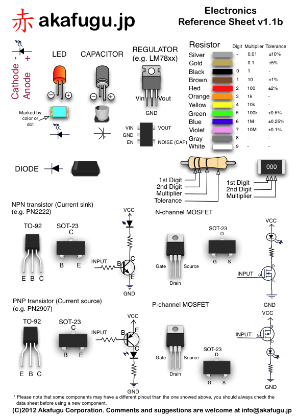
3) a LED
4) a resistor to keep the LED alive. LEDs do not like too much current, a typical 5mm led needs 150 Ohm resistor if we are running at 5 volts.
5) a single-supply, rail-to-rail operational amplifier (op-amp). I have used OPA2340 - that's Digikey part no OPA2340PA-ND. Someone should use MCP6002-I/P-ND just to try it, this one is much cheaper.
We will be using only channel B of this dual-channel amplifier.
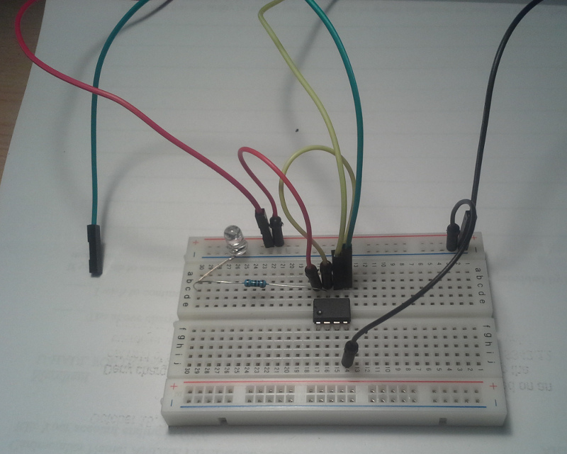
On the picture, the black wire is ground - that's pin 4 of the chip (pins are counted anti-clockwise starting from the circle mark on the plastic)
The green wire is input, it's where the hall sensor wire is connected. This green wire is connected to pin 5 of the op-amp chip.
One of the yellow wires goes from pin 6 on the op-amp to the PC6 pin on the discovery board. Another yellow wire connects pin 5 to pin 6, that's the voodoo magic of op-amps.
The red wire supplies the op-amp though pin 8.
The resistor goes from pin 7 to the longer lead of the LED. The longer lead of the LED is called anode but that's not really important
The short lead of the LED is ground.
We are expecting the LED to blink with the signal - it should be obvious blinking at idle and faster blinking if you rev it.
Tomorrow I will draw the schematic and that would make everything much more simple