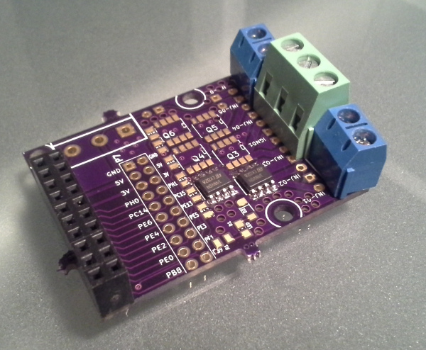
kb1gtt has finished a 6 channel injector module. It's a snap-on board for stm32f4discovery based on VNS14NV04 (35mOhm, 12A)
Couple goodies in this design: optionable LED for one of the channels. Optional resistors to drive my ignition module with one other channel. Dual-board configuration is supported.
the MOSFET we are using here is VNS14NV04 which is currently being replaced by VNS14NV04P-E
Update: the board has arrived and I have just tested it with an injector on the bench! Next step would be soldering all six channels and testing it on a car just to confirm.
I like those switches, but man are they slow.
The speed isn't an issue for injectors but with a switching time that long they're going to dissipate quite a bit more heat.
I probably would have gone with the DPAK for better dissipation.
The 150nS off time is negligible relative to the OVP decay of .5mS. The inductive energy is going to make the drivers hot. As noted in the wiki, it predicts how much heat it will need to deal with. DPaK's are harder to solder correctly, as a DIY'er will have to sit on it for a long time with an iron. This typically overheats them and causes long term problems. These SO-8's are easier for a DIY'er to do. If you have a reflow oven and temperature profile I agree DPAK's offer better thermal resistances to the heat sink.
Re: 6 channel injector module
Posted: Wed Nov 27, 2013 2:28 am
by AndreyB
I have assembled two channels and I the injector has clicked as it should click during my bench test. The board is officially functional!
Re: 6 channel injector module
Posted: Wed Nov 27, 2013 2:46 am
by AndreyB
"Diagnostic feedback through input pin."
How does this work? Is this chip grounding the input pin if case of the over-heat? Do we need a resistor between discovery and the MOSFET to protect the discovery pin?
Do I need to read the pin in pull-up mode? With pull-up mode I guess 'hi' would mean everything is fine and 'low' would mean we have an error condition?
Re: 6 channel injector module
Posted: Wed Nov 27, 2013 1:28 pm
by Sergey89
I think we really need to use a resistor before the gate to limit output current from the MCU pin.
Direct access to the gate of the Power MOSFET (analog driving)
russian wrote:Do I need to read the pin in pull-up mode? With pull-up mode I guess 'hi' would mean everything is fine and 'low' would mean we have an error condition?
You can not use pull-up resistor because it is able to open the mosfet.
Re: 6 channel injector module
Posted: Wed Nov 27, 2013 6:27 pm
by kb1gtt
The datasheet notes IISS is 100uA. It's my understanding that if the diagnostics feature is activated, the input pin will try to sink 100uA. Normally there is no current flow in the gate of a MOSFET, just the short term small stuff from the dynamics as the gate capacitance is charged. The datasheet notes Rin of 10ohms min, which I believe we are getting through the MCU drive.
Re: 6 channel injector module
Posted: Wed Nov 27, 2013 6:33 pm
by Sergey89
I think IISS is the current that used to supply internal logic and we have direct access to gate of power mosfet.
The device then behaves like a standard power MOSFET and can be used as a switch from
DC up to 50 KHz. The only difference from the user’s standpoint is that a small DC current
IISS (typ. 100 µA) flows into the input pin in order to supply the internal circuitry.
Re: 6 channel injector module
Posted: Wed Nov 27, 2013 6:36 pm
by kb1gtt
I see that Igf Fault sink current, is limited to 15mA, with out the series resistor, this may be a problem. I'll have to check the STM datasheet to make sure it can supply 15mA to 20mA. Many MCU's can provide this amount of current as it's common when driving an LED.
Re: 6 channel injector module
Posted: Wed Nov 27, 2013 7:23 pm
by Sergey89
I think it means that there is no driver before the internal power mosfet.
Re: 6 channel injector module
Posted: Wed Nov 27, 2013 7:34 pm
by kb1gtt
From pg 59 found here http://www.st.com/st-web-ui/static/active/en/resource/technical/document/datasheet/DM00086815.pdf the max that can be pulled into the MCU is 160mA, and the max each pin can source is 25mA. With a typical fault current of 15mA, and if all 6 channels fault, we could dump 90mA, or if they are all worst case drivers at 20mA, we could dump 120mA. So I think we are OK there. I'm not finding much about what the pin impedance is. If the MCU drops more than .015A(10ohm)=.15V than we have that 10ohms in the drive pin. Dropping about 1/8 of a volt when heavily driving an MCU pin is common. I guess I'll have to setup a test.
I see this board as usable with out any significant risks. However if we spin another, it would be handy to add the suggested Rin. Now if we can only find a way to get these reviews before things are sent off for MFG
Re: 6 channel injector module
Posted: Wed Nov 27, 2013 7:53 pm
by kb1gtt
While we are at it, should we make it more friendly for OPL assembly by using 0603 resistors?
Re: 6 channel injector module
Posted: Wed Nov 27, 2013 7:59 pm
by AndreyB
kb1gtt wrote:While we are at it, should we make it more friendly for OPL assembly by using 0603 resistors?
I want it OPL friendly, but not at the cost of DIY unfriendliness. 0603 is not really a DIY size
How about 8.2K 0805 resistor for pull-down and isolation?
Re: 6 channel injector module
Posted: Wed Nov 27, 2013 8:05 pm
by kb1gtt
2.2k has a Ton of 8uS while 10ohms is in the nS range. It would work for the pull down, but not for the series resistor. It really wants to be lower resistance.
Re: 6 channel injector module
Posted: Wed Nov 27, 2013 8:20 pm
by Mad Max
I was sure that Omnifet content power Mosfet and Mosfet Driver schematic.
So this is excellent solution for many cases.
I'll use VNB10N07 in my schematic (only I found in my close area)
But today Sergey89 disappoint me
He show me that this is usual Power Mosfet with output current limiter, temp and short circuit protection.
So possibly there is not enough 3.3 V to normally open Omnifet.
But as shown in "Output Characteristics" Diagram we have Ids=11A @ Vin=3V (NOT Vds !!!)
So we need Input resistor (about 10 kOhm)
Also we should use input resistor as we have Protection circuit which drops down input signal at fault.
WE NEED to test this schematic at different loads and input voltages.
Also it's possible we should use Mosfer Driver circuit for correct Omnifet drive.
Re: 6 channel injector module
Posted: Thu Nov 28, 2013 1:16 am
by kb1gtt
For VNB10N07, if your load is 1A, and you have 10A current limiter, I don't see the problem. Do you plan to use more than 1A, even a lowZ is only 5A. Unless you have a short to GND, you shouldn't approach the current limitation.
If you use closer to 10ohm instead of 10kohms, your issues with 3V will be far less. Also if you make sure to have a good GND, your issues will also be far less. I agree that MOSFET drivers can help maintain consistent Ton and Toff times, however they often aren't required if you can uphold certain other design criteria. When I use a MOSFET driver, I typically make it galvanic isolated with an op-amp. However the number of components gets significantly high, which is hard for a DIY to populate. My goal with this board is to make it easy for people to assemble with minimal tools. To obtain this goal, I'm assuming some levels of overall system design.
A series resistor of 10k is too high. I see Idss is 500uA which would result in 10k(.5mA)=5V drop. With a 3.3V supply and if you are looking for 3V to the gate, the absolute max you can have is .3v/.5mA=600 ohms. Remember your going to have some drop across your MCU high side drive, and the suggested Rin is 10 ohms. I'd recommend something more like 20 ohms.
The fault current is only 15mA to 20mA max. Each pin is capable of 25mA, so we are OK with the fault conditions. Even with 6 channels faulted, we sill don't exceed the max we can draw from the MCU power source.
Re: 6 channel injector module
Posted: Sat Nov 30, 2013 12:37 am
by AndreyB
Back to the original subject - I have tested the module in batch mode (two injectors on one channel) @ 12000 rpm
Re: 6 channel injector module
Posted: Sat Nov 30, 2013 10:09 am
by kb1gtt
Very cool, and good to see.
As a note at 9kRPM I expect each channel to produce about 3 watts of energy with an absolute max of 5 watts per channel. Do you have some temperature measurement equipment? Perhaps a multi meter with one of those temperature probes? I'd like to see when all injector channels are running, what rise in temperature you get. As well I'd like to see the variation in temperature from Q3-4 vs Q1-2. I expect that with all channels running, that Q3-Q4 will get hotter, but I don't know by how much.
Perhaps next on the list should be a thermocouple board. I would plan for a SPI interface.
Re: 6 channel injector module
Posted: Tue Dec 24, 2013 3:49 am
by AndreyB
Status update: I have updated the first post of this thread with rev 0.2 which has the resistor issue address, rev 0.2 has no known issues.
Re: 6 channel injector module
Posted: Wed Jan 29, 2014 3:40 pm
by AndreyB
Digikey & Mouser Bills Of Material (BOM) added to the top post
Re: 6 channel injector module
Posted: Wed Jan 29, 2014 4:00 pm
by hasse.69
How verry nice
//Hasse
Re: 6 channel injector module - VNS14NV04
Posted: Wed Apr 22, 2015 6:59 pm
by jhm
VNS14 are good choice. They are fast enough to do 10kHz PWM for LPG injectors (used in BRC equiment)
The only you should do - improve cooling capabilities: make board larger, maximize trace size, place hole arrays for heat transfer to bottom copper