coil on spark, bench setup: noise issues

Hardware inside and outside of the ECU
User avatar
AndreyB
Site Admin
Posts: 14325
Joined: Wed Aug 28, 2013 1:28 am
Location: Jersey City
Github Username: rusefillc
Slack: Andrey B

coil on spark, bench setup: noise issues

Post by AndreyB »


That's the 6th channel with a 150 Ohm pull-up to five volts.

The spark is there and everything is great, but the problem is that some noise is getting back into the chip a) stm32 device keeps to constantly connect and disconnect from the PC b) you see how on the sniffer the simulated signal gets messed up - sometimes instead of 1500 rpm it shows 3000 rpm - that's noise making it's way to the capture pins c) eventually the serial gets disconnected. For instance, on this frame - there should not be a line on the upper wave.

Image

While this is not exactly the setup I have on the car, I suspect I have similar noise issues while running the car. Question: how do we fix this? :)
Very limited telepathic abilities - please post logs & tunes where appropriate - http://rusefi.com/s/questions

Always looking for C/C++/Java/PHP developers! Please help us see https://rusefi.com/s/howtocontribute
User avatar
kb1gtt
contributor
contributor
Posts: 3758
Joined: Tue Sep 10, 2013 1:42 am
Location: ME of USA

Re: 6 channel injector module

Post by kb1gtt »

The coil on plug will pull massive amounts of current, and when powered via the STM board, it likely exceeds the boards ability to provide that power. You could try a massive cap preferably at the pencil coil across the 5V lines. It looks like you are USB powered, I seem to recall USB can only provide a max of .5A.

Also try adding a GND strap from the coil, to closer to the GND on the pencil. Right now your spark return currents need to circulate in a much larger loop than required. Try to keep that loop minimal.

Also do you have more details on your RPM simulation setup? I think I see a secondary STM connected. I'm mostly wondering what the impedance of that is. It's easier for noise pulses to get into a high impedance input, than it is for a low impedance input. I think you probably have a reasonably low impedance input, so I don't expect any real RF coupling. I suspect the issue is largely caused by a soft 5V supply, and / or poor current loop control.
Welcome to the friendlier side of internet crazy :)
User avatar
AndreyB
Site Admin
Posts: 14325
Joined: Wed Aug 28, 2013 1:28 am
Location: Jersey City
Github Username: rusefillc
Slack: Andrey B

Re: 6 channel injector module

Post by AndreyB »

kb1gtt wrote:The coil on plug will pull massive amounts of current, and when powered via the STM board...
C'mon, I am not that bad!

Image

This is a three-wire coil with a build-in igniter, I should have mentioned that explicitly. We have GND, +12 going to a +12 power supply (old desktop power supply unit) and a +5 logic level control wire.

This is NOT the same coil as in previous video. On the previous video there was a Toyota two-wire coil coil with external igniter . Here we have a three-wire Nissan which has individual igniters inside the module.
Very limited telepathic abilities - please post logs & tunes where appropriate - http://rusefi.com/s/questions

Always looking for C/C++/Java/PHP developers! Please help us see https://rusefi.com/s/howtocontribute
Mad Max
Posts: 187
Joined: Wed Nov 13, 2013 12:34 pm
Location: Ukraine, Kharkov

Re: 6 channel injector module

Post by Mad Max »

At begin of charging any ignition coil take a current 6-12 A which drop down in charging time.
So there isn't enough desktop power unit.
If you want to use 3-5A power supply you should use any 12V battery 5-15 AH in parallel to 12V power unit.
Otherwise you need 12V 20A power unit.
Skype- max.mad486
User avatar
AndreyB
Site Admin
Posts: 14325
Joined: Wed Aug 28, 2013 1:28 am
Location: Jersey City
Github Username: rusefillc
Slack: Andrey B

Re: 6 channel injector module

Post by AndreyB »

I have re-tested this with separate power supplies:

+12 coil and +5v for the injector board are coming from my spare desktop power supply
discovery is powered via USB by my primary desktop
everything is on the same ground

Unfortunately, same noise issue :( If I am less tired tomorrow I will feed the coil of a car battery, just to check this scenario.
Very limited telepathic abilities - please post logs & tunes where appropriate - http://rusefi.com/s/questions

Always looking for C/C++/Java/PHP developers! Please help us see https://rusefi.com/s/howtocontribute
User avatar
kb1gtt
contributor
contributor
Posts: 3758
Joined: Tue Sep 10, 2013 1:42 am
Location: ME of USA

Re: 6 channel injector module

Post by kb1gtt »

Can you shorten the GND loop from the pencil coil? In the video it appears you have that connected to the driver board's screw terminal. That's probably lifting when the spark current pass through the GND. If it lifts by only a couple V, it will cause the pin to detect as high instead of low.

Also do we have a way to verify the pulse is from hardware as opposed to software. Could be an odd software bug. I think your correct that it's hardware, but should always consider both sides of the fence.

Can you overlay the signal that generates the spark pulse? For example, do you see a consistent timing between the pulse and the blip?
Welcome to the friendlier side of internet crazy :)
User avatar
AndreyB
Site Admin
Posts: 14325
Joined: Wed Aug 28, 2013 1:28 am
Location: Jersey City
Github Username: rusefillc
Slack: Andrey B

Re: 6 channel injector module

Post by AndreyB »

kb1gtt wrote:Can you shorten the GND loop from the pencil coil? In the video it appears you have that connected to the driver board's screw terminal. That's probably lifting when the spark current pass through the GND. If it lifts by only a couple V, it will cause the pin to detect as high instead of low.
I am not sure what you mean exactly, I will probably call you later today.

This is definitely not a software issue because I am not controlling the ST LINK connection in any way, and this connections comes and goes in the 'noisy' setup. ST LINK is expected to stay connecter no matter what

An update: @ made a point to use a real battery, not a secondary desktop power supply - and this HAS made a difference: if powered by a real battery, and if the mosfet pull-up also goes to same +12 from the battery, at least both USB connections are stable (ST LINK does not disconnect anymore and serial-over-USB also stays connected). This is progress! With the wall power supply, applying +12 to the mosfet pull up did NOT make much difference, it has to be the battery for some reason.
Very limited telepathic abilities - please post logs & tunes where appropriate - http://rusefi.com/s/questions

Always looking for C/C++/Java/PHP developers! Please help us see https://rusefi.com/s/howtocontribute
User avatar
AndreyB
Site Admin
Posts: 14325
Joined: Wed Aug 28, 2013 1:28 am
Location: Jersey City
Github Username: rusefillc
Slack: Andrey B

Re: coil on spark, bench setup: noise issues

Post by AndreyB »

Status update:

I have re-wired the GND to 'shorten the loops'
1) coil GND now goes directly to spark plug GND
2) spark plug GND goes directly to battery GND terminal
3) stm32 GND is a different wire coming right from battery GND terminal
Image

Also in this setup I have un-plugged the driver board from stm32 so that I can use +12 coming from the battery as the pull-up voltage for the control line
Image

And there is still some noise. Look for the vertical lives within the position sensor waves - they should not be there. Also I see a correlation - the vertical black lines on the waves are always happening around the coil discharge
Please click this link to see a screenshot - the picture gets truncated if I try to embed it here

On the screenshot there are three examples of the noise on the primary sensor channel and one example on the secondary channel.
Very limited telepathic abilities - please post logs & tunes where appropriate - http://rusefi.com/s/questions

Always looking for C/C++/Java/PHP developers! Please help us see https://rusefi.com/s/howtocontribute
User avatar
kb1gtt
contributor
contributor
Posts: 3758
Joined: Tue Sep 10, 2013 1:42 am
Location: ME of USA

Re: coil on spark, bench setup: noise issues

Post by kb1gtt »

We really need to get you a scope of some kind. A $7 USB sound card and a DIY interface goes a long way. http://www.electronicsfaq.com/2010/05/poor-students-oscilloscope.html is a good reference. I suggest the CM108 chip set. Also good reference http://www.automata.hk/projects/scope this interface is a bit better http://xoscope.sourceforge.net/hardware/pictures.html and the USB sound card found here http://www.ebay.com/itm/Audio-Sound-5-1CH-Blue-Card-External-Adapter-USB-2-0-to-Mic-3D-New-Speaker-E456-/271265265387?pt=US_Sound_Card_External&hash=item3f28ab76eb

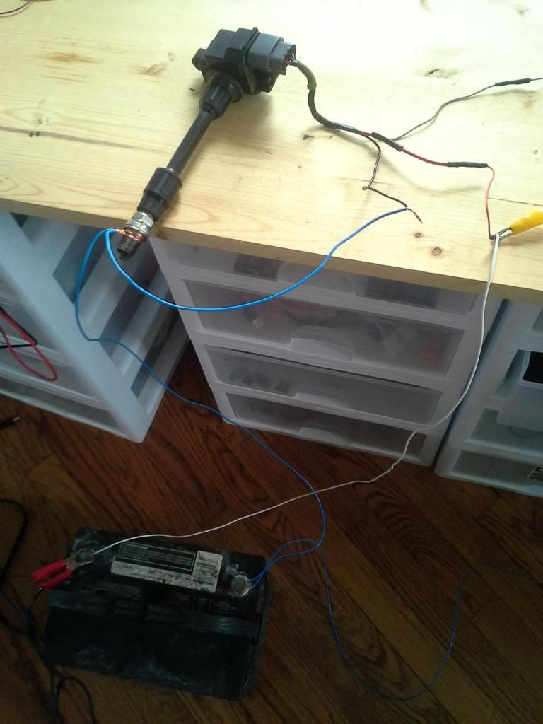
Any how, that said, the high voltage GND loop is much smaller and the voltage drops from the spark currents shouldn't be pulling the STM GND up any more. Well at least from a DC standpoint. Assuming the issue is still a bad GND, you can try taking that wire between the battery - and the coil and wrap it around a nail or some kind of small iron object, or if that's hard to find pencil or something would be better than nothing. The goal is to make that GND wire into a kind of small coil. Coils don't like to change current, and such a small coil will help choke off RF from the coil potentially preventing RF from spreading to other things on the wire. I'm a skeptic it will help significantly, but eh, won't hurt, so might as well try it. I'm also assuming you don't have an RF choke similar to this. https://www.google.com/search?sourceid=chrome&client=ubuntu&channel=cs&ie=UTF-8&q=ferrite+bead#channel=cs&q=ferrite+bead&tbm=shop

There is still a chance the issue is a bad GND, especially when I don't know the tech inside the coil on plug. Is that an OVP MOSFET, IGBT with snubbing diode, ect. I'm basically guessing at large portions of the circuit. My next guess would be that it's not the GND. If there is some kind of spike, that could be coming back up the low voltage signal wire. Perhaps add a diode in series with that signal wire to help block that kind of kick back from making it back to the STM. I guess also try the same for the 12V supply. But try it on the signal wire first. The goal is to only allow current to flow one way, and prevent current from flowing the other way.

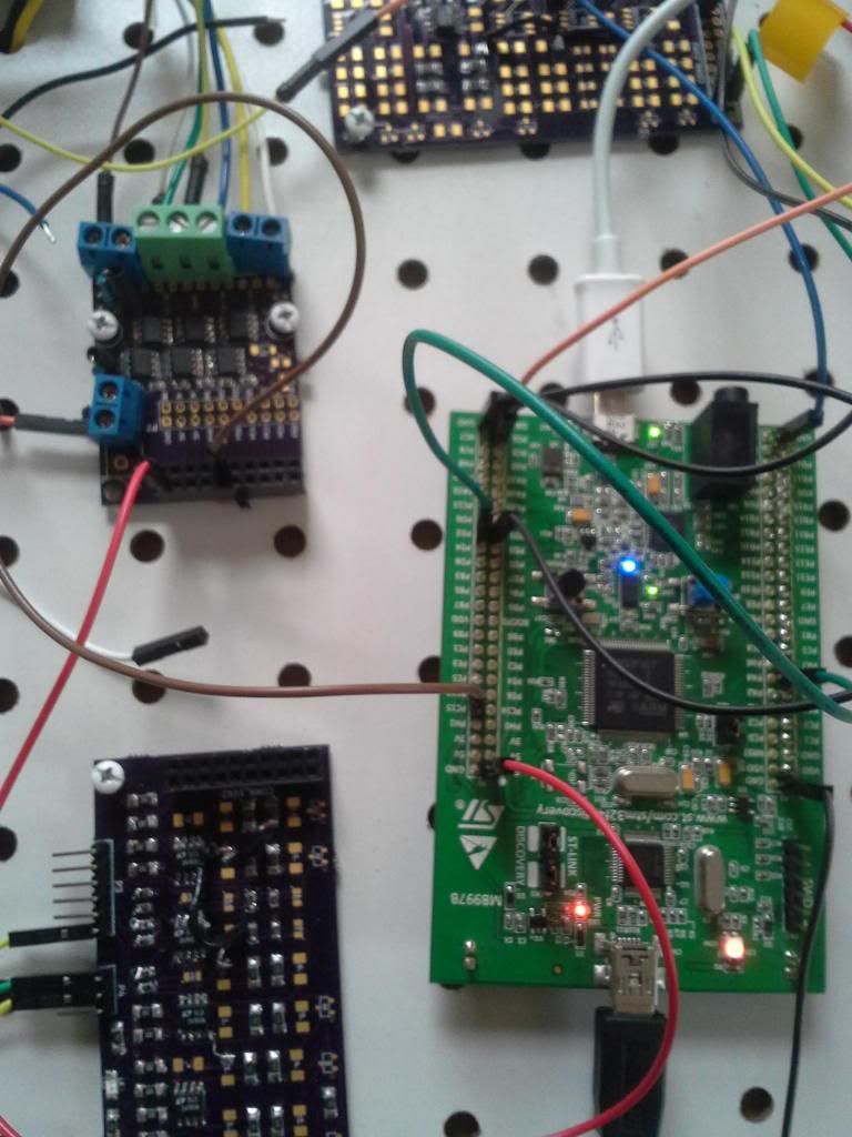
Also how is the STM powered? Do you have a 5V regulator that's powered off the battery - terminal? I see both USB ports, I wonder if the PC might be floating relative to the battery. All you need to create an issue is for the STM to lift by like 1 to 2V, or for the rail voltage to drop 2 to 3 V for a short period of time.

If you had a scope, you could look for GND issues by connecting the scope GND to the battery terminal, then use the other scope lead to check various GND points. I wonder if a multimeter might help. Most multimeters are for very low frequencies so I would expect it would not detect such a short pulse. However it might be worth a try. Couldn't hurt. Using the MAX setting can often catch a short term pulse, but often it does not.
Welcome to the friendlier side of internet crazy :)
puff
contributor
contributor
Posts: 2961
Joined: Mon Nov 11, 2013 11:28 am
Location: Moskau

Re: coil on spark, bench setup: noise issues

Post by puff »

there are two inputs for triggers, right?
remember my video report on the buggy devconsole - it was just a cps pin wire connected to nowhere on the other side, and I got plenty of noise there right from nowhere. if dodge neon's config utilizes the second trigger pin, it could easily cause this behavior? btw, in my case i didn't notice any disconnects - just rpm was sometimes twice as less than needed.
my dad believes, the spark was weak. however, I guess it was just 12V (not 14 and something on the properly working engine), and the dwell time was 4ms. I guess I should have increased it.
probably we need a separate tab in dev console with buttons for each available function, with the whole screen divided into several sections: general, ignition, fueling, etc. ;-)
User avatar
AndreyB
Site Admin
Posts: 14325
Joined: Wed Aug 28, 2013 1:28 am
Location: Jersey City
Github Username: rusefillc
Slack: Andrey B

Re: coil on spark, bench setup: noise issues

Post by AndreyB »

I've added

Code: Select all

engineConfiguration->needSecondTriggerInput = FALSE;
into Neon config - 2nd channel should be totally ignored now.
Very limited telepathic abilities - please post logs & tunes where appropriate - http://rusefi.com/s/questions

Always looking for C/C++/Java/PHP developers! Please help us see https://rusefi.com/s/howtocontribute
puff
contributor
contributor
Posts: 2961
Joined: Mon Nov 11, 2013 11:28 am
Location: Moskau

Re: coil on spark, bench setup: noise issues

Post by puff »

next month gonna try optocouplers.
4n35 in smd package should be sufficient?
how do we make sure that without trigger signal there is no logic 1 on the ignition module? (with optocoupler it would probably be inverted?)
Sudo
Posts: 92
Joined: Mon Mar 17, 2014 12:53 am

Re: 6 channel injector module

Post by Sudo »

russian wrote:I have re-tested this with separate power supplies:

+12 coil and +5v for the injector board are coming from my spare desktop power supply
discovery is powered via USB by my primary desktop
everything is on the same ground

Unfortunately, same noise issue :( If I am less tired tomorrow I will feed the coil of a car battery, just to check this scenario.
Hmm I am curious, for the electronics side, do you have the battery ground going to the driver board first or the STM32 board first? I would suggest making your driver board the common node for ground.
puff
contributor
contributor
Posts: 2961
Joined: Mon Nov 11, 2013 11:28 am
Location: Moskau

Re: coil on spark, bench setup: noise issues

Post by puff »

well, in my case here's the video:
[video][/video]
basically, the ground from discovery, ground from the ignition module and from the plugs - they are three different grounds coming to the junction right on the battery.
Last edited by puff on Tue Apr 01, 2014 11:17 pm, edited 1 time in total.
User avatar
kb1gtt
contributor
contributor
Posts: 3758
Joined: Tue Sep 10, 2013 1:42 am
Location: ME of USA

Re: coil on spark, bench setup: noise issues

Post by kb1gtt »

It's probably a combination of current loops and voltage drops. Remember the coil will draw some 10A or above, and those wires look fairly small. I would be the voltage is dropping during the dwell, and then when it fires, it there is a bunch of RF generated as the current loop is reasonably large for that loop.

What are you using to generate the RPM signal? Is it VR or Hall? If it's Hall, where is the pull up resistor physically located? It is preferable for that to be located close to the STM.
Welcome to the friendlier side of internet crazy :)
puff
contributor
contributor
Posts: 2961
Joined: Mon Nov 11, 2013 11:28 am
Location: Moskau

Re: coil on spark, bench setup: noise issues

Post by puff »

in this case the trigger signal is coming from PD1 or PD2.
I should have measured the current consumption of this module…
User avatar
kb1gtt
contributor
contributor
Posts: 3758
Joined: Tue Sep 10, 2013 1:42 am
Location: ME of USA

Re: coil on spark, bench setup: noise issues

Post by kb1gtt »

Ah, so I seem to recall that's a fairly hard drive from + to GND with a very short wire on the STM board, jumpering two GPIO together. I would then say this is very likely a voltage drop issues. I would suggest a large bulk cap near the STM board, as well as a ceramic cap. The bulk cap will help ride out voltage drops and such ripple caused by the longer term effects of the dwell, and the ceramic helps with the short term drops due to RF kind of stuff. Basically the STM will look to draw some very short term current, and the small cap will make sure it can get the higher frequency components. So you probably need both a bulk cap and decoupling cap.
Welcome to the friendlier side of internet crazy :)
puff
contributor
contributor
Posts: 2961
Joined: Mon Nov 11, 2013 11:28 am
Location: Moskau

Re: coil on spark, bench setup: noise issues

Post by puff »

oops. two years have passed and here i am once again. reread your message again and again. could you please explain what is the reason for that voltage drop?
here's this fall's movie
just pc6<>pd1 wire, two signal wires + one ground wire to the ignition module. discover is powered from the cell phone charger, ignition module runs on the car battery. I have the whole weekend to play with it. when the battery is disconnected I see nice and clean ignition signals on my logic analyzer. once I connect the battery, the signal becomes noisy.
User avatar
kb1gtt
contributor
contributor
Posts: 3758
Joined: Tue Sep 10, 2013 1:42 am
Location: ME of USA

Re: coil on spark, bench setup: noise issues

Post by kb1gtt »

That broken part of the frame may be causing a significantly larger current loop than the other side of the spark. This larger loop could be causing magnetic coupling, to the GND wires, but I doubt it. I suspect it's mostly a voltage drop issue. The coil discharge is higher frequency, higher current. A resistance of as little as 0.1 ohms of impedance (not just ohms but AC ohms) can cause a voltage drop of 1V. The STM is 3V, so that would be a problem.

I wonder if I should draw up a GND voltage sniffer. I'm thinking of a device that you connect to the battery GND, then work your way around your circuit. If the probe voltage is more than some set threshold like 0.010 V, then it triggers an LED for a couple seconds, such that you can traced down sources of noise spikes. It is best to have a scope. Then when referencing the battery - work your way around your circuit looking for where the voltage starts to get away from GND. With out a scope this become very difficult.

Is your STM GND connected directly to the battery?
Same goes for the coil, is that directly connected to the battery?
Also is your frame directly connected to the battery?

When I say direct I mean direct, no daisy chain GND connections, no crimped splices. Best if you can have a normal battery terminal and ring terminals on each wire. No multiple wires in one crimp. Individual rings on all GND wires. Also if you have to make extensions for your coil harness, best to solder on the extension, then put a ring on the wire connected to the battery.

Do you have a scope which can allow you to look at where the voltage is changing?
Welcome to the friendlier side of internet crazy :)
puff
contributor
contributor
Posts: 2961
Joined: Mon Nov 11, 2013 11:28 am
Location: Moskau

Re: coil on spark, bench setup: noise issues

Post by puff »

that sort of ground analyzing device would be handy!

here's what my progress (no progress) tonight:


That crack in the frame - there is no gap, it's bridged.
And no, I don't have scope :-( Just learned today, my dad's friend has got one, but it might take some time to bring that here... :-(
User avatar
kb1gtt
contributor
contributor
Posts: 3758
Joined: Tue Sep 10, 2013 1:42 am
Location: ME of USA

Re: coil on spark, bench setup: noise issues

Post by kb1gtt »

Is the problem that the sparks are not as consistent as you expect, or that there is a change in RPM because of the noise? I'm not fully following what the problem is. In the above there was talk about how the ignition events were causing erroneous RPM's to be decoded. Is that sensed RPM still the problem, or is there a different problem.

Do you have a schematic or similar information for that coil pack? I wonder if the STM has enough drive to power that device.
Welcome to the friendlier side of internet crazy :)
puff
contributor
contributor
Posts: 2961
Joined: Mon Nov 11, 2013 11:28 am
Location: Moskau

Re: coil on spark, bench setup: noise issues

Post by puff »

The problem is the spark is not as consistent as I expect. When I connect my logic analyzer to those ignition outputs on discovery, when I power the ignition module, I see lotsof noise. Instead of consistent signal I see lots of spikes of various duration, etc. I am not sure if this noise comes from the firmware (i.e. the analog inputs work as antennas, the firmware receives this erroneus information and tries to adjust ignition respectively. say, what happens with ignition if disco sees a spike in map readings, or a sudden drop in clt?), or it's a hardware generated noise on the outputs. Besides, yesterday it happened so that I had the tunerstudio connected to the board, and when I powered ignition on, I started getting disconnected from the tunerstudio...
Here's what's inside that module.
Attachments
shema3.jpg
shema3.jpg (40.88 KiB) Viewed 18624 times
User avatar
kb1gtt
contributor
contributor
Posts: 3758
Joined: Tue Sep 10, 2013 1:42 am
Location: ME of USA

Re: coil on spark, bench setup: noise issues

Post by kb1gtt »

Do I recall VD1 and VD2 were external?

Do you have the logic sniffing to look at?

I would suggest putting some resistors on the analog inputs. Those appear to be not terminated right now so they are very high impedance and very suitable to noise. They would be far less noisy if they had some resistors to GND or a small POT to set them to some level.
Welcome to the friendlier side of internet crazy :)
puff
contributor
contributor
Posts: 2961
Joined: Mon Nov 11, 2013 11:28 am
Location: Moskau

Re: coil on spark, bench setup: noise issues

Post by puff »

No, VD1 and VD2 are inside the module. look through the pictures here: http://www.autoelectric.ru/advices/ignition/ignition.htm

I have a logic sniffer, but what exactly you want to look at? those ugly noisy ingition outputs? you don't trust me? :D

as for analog resistors - probably, this makes some sense. could their high impedance in noisy environment lead to discovery reboots? (why I get tuner studio disconnects when I power on my ignition module?)
btw, with arduino it worked flawlessly. In the russian part of the forum guys suggested to plug in frankenstein board.but as of today I only have three opamps there, without any input circuitry on all of the inputs but for VBAT. and, which is much worse, you remember the pics of my frankenstein after a year in the drawyer... not sure if it would work at all, but if you say this might help - I'd prefer to solder some voltage dividers on the inputs there and give it a try.
User avatar
kb1gtt
contributor
contributor
Posts: 3758
Joined: Tue Sep 10, 2013 1:42 am
Location: ME of USA

Re: coil on spark, bench setup: noise issues

Post by kb1gtt »

I trust there is a problem, I'm not sure what it is. If it's analog issues, I would expect to see the dwell on the output pulses. If it's over current on the output I would see a different patter in the noisy pulses. I was wondering what we might see in those pulses that might offer some insight into the problem.

I would think that if it's noise on the analog, you could see that on the rusEfi Console. Can you get a log from the console. Does it last long enough before it disconnects?

The USB disconnects are currently unknown. I suspect it's because of GND noise but that's only a guess.
Welcome to the friendlier side of internet crazy :)
puff
contributor
contributor
Posts: 2961
Joined: Mon Nov 11, 2013 11:28 am
Location: Moskau

Re: coil on spark, bench setup: noise issues

Post by puff »

Ookay, now i see. I'll make the log from the logger analyzer. I can't get a log from the console - it just keeps disconnecting even without anything connecte to it (but tuner studio works perfectly fine). so, only from my logic analyzer.
puff
contributor
contributor
Posts: 2961
Joined: Mon Nov 11, 2013 11:28 am
Location: Moskau

Re: coil on spark, bench setup: noise issues

Post by puff »

here's the log. this time - from the battery charger (plain transformer - the battery itself is in the car now)
4 MHz, 60 M Samples [1].logicdata
(16.25 KiB) Downloaded 737 times
User avatar
AndreyB
Site Admin
Posts: 14325
Joined: Wed Aug 28, 2013 1:28 am
Location: Jersey City
Github Username: rusefillc
Slack: Andrey B

Re: coil on spark, bench setup: noise issues

Post by AndreyB »

Assuming channels #0 and #2 are wasted spark (channel names would obviously help in the future) looks like something is not right - what are these random irregularities?

Also there is a strange shift between channels - not 180 degrees as I would expect, but that's probably trigger issues.
Attachments
screenshot.png
screenshot.png (59.34 KiB) Viewed 18592 times
Very limited telepathic abilities - please post logs & tunes where appropriate - http://rusefi.com/s/questions

Always looking for C/C++/Java/PHP developers! Please help us see https://rusefi.com/s/howtocontribute
puff
contributor
contributor
Posts: 2961
Joined: Mon Nov 11, 2013 11:28 am
Location: Moskau

Re: coil on spark, bench setup: noise issues

Post by puff »

probably this means that the board continues to work (no reboots), but there's noise on those wires. May be I'd try with ferrite beads as abricos suggested?
User avatar
kb1gtt
contributor
contributor
Posts: 3758
Joined: Tue Sep 10, 2013 1:42 am
Location: ME of USA

Re: coil on spark, bench setup: noise issues

Post by kb1gtt »

What was each channel connected to? Was the brown, orange and yellow channel connected to anything? I think that black and red are the only channels of interests is that correct? Where were those connected when you took the readings? Was that at the STM output, or the coil input?
Welcome to the friendlier side of internet crazy :)
Post Reply