Page 1 of 8
Power supply - kb1gtt
Posted: Sat Jan 04, 2014 12:59 pm
by AndreyB
Another power supply design - this one by
@
 SVN Repository
Schematics
BOM
SVN Repository
Schematics
BOM
Re: Power supply - kb1gtt
Posted: Sat Jan 04, 2014 8:30 pm
by hasse.69
Re: Power supply - kb1gtt
Posted: Sat Jan 04, 2014 11:48 pm
by kb1gtt
I'm not sure about the tant, it needs to be low ESR, preferably the same as the AVX TPS part I noted. It's probably good enough. If it's not perfect, I would expect it would increase the ripple, and increase how much heat it makes.
The buck regulator is spot on, and much lower cost than the traditional supplier. I wonder about shipping.
The coil is not correct, it's 53uH needs to be 38uH, the datasheet listed the pulse part number and claimed it was 33uH however pulse claims the part number is 38uH not 33uH, I suspect a typo in the data shseet.
Re: Power supply - kb1gtt
Posted: Mon Jan 06, 2014 12:40 am
by AndreyB
Re: Power supply - kb1gtt
Posted: Mon Jan 06, 2014 10:53 am
by kb1gtt
The LM2596S is very clear about the components they suggest. We don't have to use those components, but if we don't it will probably take some trail by error and will probably decrease the efficiency and increase the ripple. I have two of those low cost buck regulator, I'll have to check it's efficiency, ripple and such. My initial reaction is that the 100uf is probably to small to work at a 3A load and the ripple is probably larger than what's noted on the datasheet. The 330uH is way wrong according to the datasheet. With that pre-made buck regulator, I've noticed some issues with long term stability that aren't mentioned in the datasheet. I can set this thing really accurately, then over the course of a minute or two it seems to wonder a bit. Not much but about .1V.
From this link
http://datasheet.octopart.com/LM2596S-5.0/NOPB-Texas-Instruments-datasheet-10621667.pdf look at page 13, the uF ranges from 22 uF to a max of 150 uF. In our case the suggested inductor is L40, as noted on page 17, figure 5. This means on page 13, they suggest either a 330uF 35V electrolytic, or a 220uF 10V tant. I believe the key they are looking for is the capacitors internal ESR which is 100 mohm for the tant. However when selecting the input capacitor, they also are concerned with the RMS current rating of the cap. So they may be looking for additional parameters in this section.
So based on the datasheet, I would say no 330uH is not good, and the 220uF tants might be OK, but I'd need to check the ESR. I expect the ESR will probably be a bit higher than the one I put in the BOM. This higher ESR would result in inefficiencies, and may effect ripple. Remember the power is (I^2)R, so at (3A^2).1ohm = .9W, if you double the ESR to say .2 ohms, then you jump up to 1.8 watts dissipated by just the capacitor.
I would bet any of these would be OK. They are 220uF-ish tants with a 10V min DC voltage, and below 100 mohm ESR.
http://octopart.com/partsearch#!?filter%5Bfields%5D%5Bcategory_uids%5D%5B%5D=4c11811b7d3097d6&filter%5Bfields%5D%5Bspecs.capacitance.value%5D%5B%5D=%5B0.00021799999999999999%20TO%200.00022999999999999998%5D&start=0&limit=10&filter%5Bfields%5D%5Bspecs.dielectric_material.value%5D%5B%5D=Tantalum&filter%5Bfields%5D%5Bspecs.voltage_rating_dc.value%5D%5B%5D=%5B10%20TO%201000000%5D&filter%5Bfields%5D%5Bspecs.equivalent_series_resistance_esr.value%5D%5B%5D=%5B0.0025%20TO%200.101%5D&sortby=avg_price%20asc
Most of those have an ESR of 100 mohms, but this one has 60 mohms.
http://octopart.com/tpse227m010r0060-avx+interconnect+%2F+elco-8716379
Re: Power supply - kb1gtt
Posted: Mon Jan 06, 2014 11:37 am
by kb1gtt
For the inductor, I would say the critical parameters are 33uH to 38uH as well as rated for at least 3A and less than 50 mohms. It would also be good if the self resonant frequency is close to 150 kHz and also good if it can be surface mount. I found one via octopart
http://octopart.com/pm2120-330k-bourns-395438 It looks to cost about $2 instead of $6. So that's a better price and much closer to the datasheet than the 330 uH used on the low cost ebay/china module. It's a blah that it's not in stock.
I got my module from seeedstudio
http://www.seeedstudio.com/depot/adjustable-dcdc-power-converter-125v-35v3a-p-1534.html
Re: Power supply - kb1gtt
Posted: Tue Jan 07, 2014 12:14 am
by kb1gtt
If we find an alternative set of caps, inductor and diode, I could make a board that accepts both components. Then I could populate one with the parts from the datasheet, and the other board with lower cost parts. Then I could compare the before and after to see how the ripple and efficiency changes.
Re: Power supply - kb1gtt
Posted: Tue Jan 07, 2014 5:21 am
by blundar
This is what I've used in the past. I don't think I broke $10 in components, but it was probably close. It's not as spiffy as what's been proposed here in many ways but it was specified to take 0 to 48 volts input and also be safe with reverse polarity at full 48v.
I use eagle... Sorry. I can post .sch files from eagle if anyone wants them.
Re: Power supply - kb1gtt
Posted: Tue Jan 07, 2014 10:53 am
by kb1gtt
The issue with linear designs is mostly thermal issues. If you draw say 3A, when you drop from 14V to 5V, you are dissipating 9V*3A=27 watts of energy you have to remove from the control unit. when your injector drivers are also going to be dumping a couple watts per channel, this can become a real issue. Or if you make your PCB design reasonably small, the energy densities become a real issue to work with. I'm looking for an automotive qualified design, which requires better efficiency of the power supply. Also this wasted energy is a blah for motorcycles and other such devices with a constrained electrical supply.
Re: Power supply - kb1gtt
Posted: Tue Jan 07, 2014 1:37 pm
by AndreyB
How many "chicken and egg" issues do we have here?

1) for the time being, we need 5V because for the time being we are using stm32f4discovery
2) on the other hand, we are getting closer to +3.3 analog inputs - so, if analog goes forward we would need 3.3V power supply already to run it
Should we focus on the 3.3 power supply? We can use something off the shelf for 5v since this looks to be temporary
Re: Power supply - kb1gtt
Posted: Tue Jan 07, 2014 3:21 pm
by blundar
I have about a dozen different ECUs downstairs right now (Honda OBD1, Honda OBD2, Nissan OBD1, Nissan OBD2, Honda OBD2, Ford OBD1, Ford OBD2, Ford Diesel ECM, Ford Diesel FICM, GM OBD2, Audi OBD2, BMW OBD1, ...)
EVERY SINGLE ONE uses a LDO style regulator mounted on the case or a large thermal pad on the ECU.
kb1gtt, I agree that efficiency is important when you have multiple amp power supplies. However, this should never be the case with a properly designed ECU. All of the switching on these units is done on the GROUND side (NPN Darlington / N-FET). AFAIK, the main reason for this is so that it removes the need for a large power supply in the ECU from which to source current. The examples you bring up of needing a larger power supply don't ring true.
Typically, injectors are wired with VBat+ on one pin and the ECU providing pull-up float (off) or sink to ground via FET/Darlington (on).
Typically, creative power sourcing/wiring for H Bridges can eliminate the need for the ECU to source any serious current.
Most of the ECUs in my junk bin have <1A total power output from the LDO regulator and they're able to run the whole ECU comfortably without heat issues because the ECU is not wired as a current source, rather as a current sink.
If I'm missing something, please tell me to RTFM. I've been doing automotive electronics design for a while but I'm quite new here and haven't had a chance to wrap my head around the extent of the project and its full needs.
Respectfully,
-Dave
Re: Power supply - kb1gtt
Posted: Tue Jan 07, 2014 5:58 pm
by kb1gtt
Hmmm, must not run analog gauges, as those typically are driven by the ECU.
For 3.3V, I'd run a linear after the 5V.
Re: Power supply - kb1gtt
Posted: Tue Jan 07, 2014 6:33 pm
by AndreyB
my mazdas have mechanical speedo. Not sure about tach. Coolant gauge has its own sensor.
Mini has can gauges.
Could it be that between the older mechanical and newer CAN not so many cars drive a lot of gauges?
Re: Power supply - kb1gtt
Posted: Tue Jan 07, 2014 9:56 pm
by blundar
You can power gauges by external power. Putting a beefcake PSU inside the ECU for external gauges makes little sense to me. What kind of design parameters are we working around here for PSU? I'm not trying to be difficult / rude, just trying to grasp what is the goal. If there is a place for me to RTFM this, please point me at it.
Re: Power supply - kb1gtt
Posted: Tue Jan 07, 2014 10:04 pm
by AndreyB
I am afraid there is no formal M for this so far
I have started an online spreadsheet - let's figure out what our needs are:
Re: Power supply - kb1gtt
Posted: Wed Jan 08, 2014 10:31 am
by kb1gtt
Around here some where there's a link got ISO 7637, it provides a bunch of details in what's required to be an automotive qualified design. I made a .25 amp supply which can be found as part of the board here.
http://daecu.googlecode.com/svn/Hardware/trunk/KICAD_Project_TRK-MPC5634_P3-P4-ETPU_IO_proto/TRK-MPC5634_ETPU_IO-board-sch_RA.pdf Sorry my ISP sucks so browsing the web right now is a bugger and very time consuming for me to find the link to the tread. Even at a 10V drop and and .25A the board needs to dissipate 2.5 watts.
I've got a couple newer ECU's mostly with the 5554 chip at it's core. They use switch mode supplies, and don't have the external gauges. I suspect they are capable of 3A as the inductor is quite large. From what I've seen most switch mode chips that claim automotive qualified are around the 3 to 5 amp capacity. So I figured that because a .25A and 3A supply cost about the same, might as well get the 3A as it seems common that it's needed.
Re: Power supply - kb1gtt
Posted: Sat Feb 22, 2014 2:16 pm
by hasse.69
Re: Power supply - kb1gtt
Posted: Sat Feb 22, 2014 3:16 pm
by AndreyB
Here is the same item from their eBay store
I've talked to Jared and he will have a look at this supplier to see if we can get more then just the inductor from them. Thanks for the great link!
Re: Power supply - kb1gtt
Posted: Fri Feb 28, 2014 8:26 pm
by kb1gtt
We would get a lower cost BOM if use this
http://www.sky-macau.com/ as one of the suppliers. I have updated the BOM below.
- 1 2 3817361683 INDUCT PWR 38UH 3.0A 150KHZ SMD $.70
2 2 8702041755 CAP TANT 220UF 10V 20% 2917 $.45
3 1 6841999795 IC REG BUCK 5V 3A TO263-5 $.70
4 1 PCE3523CT-ND CAP ALUM 680UF 50V 20% SMD $2.17
5 1 VS-50WQ04FNPBF-ND DIODE SCHOTTKY 40V 5.5A DPAK $1.47
6 1 MMBZ18VALT1GOSCT-ND TVS DIODE 14.5VWM 25VC SOT23 $0.25
7 1 FQD7P06TMCT-ND MOSFET P-CH 60V 5.4A DPAK $0.65
Total = $7.54 USD
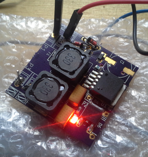
I just ordered from the e-bay store, so I'll have parts to verify shortly-ish.
Re: Power supply - kb1gtt
Posted: Fri Feb 28, 2014 9:49 pm
by puff
just 8 bucks plus delivery costs and you get a decent pwer supply? that's nice!
Re: Power supply - kb1gtt
Posted: Fri Feb 28, 2014 10:06 pm
by kb1gtt
That's in qty 1, the price goes down if you do a batch of 10. Probably decreases by around 20%, perhaps more. Those folks also populate prototype boards, I'd be interested in seeing what the total cost with assembly is.
Re: Power supply - kb1gtt
Posted: Sat Mar 01, 2014 1:45 pm
by puff
still we need a board?
i'm not in a hurry - still hoping for a large board that will include everything and even more.
Re: Power supply - kb1gtt
Posted: Sat Mar 01, 2014 4:19 pm
by kb1gtt
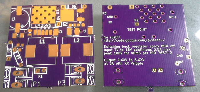
I ordered the components so I can measure the pads, which will then let me make a board layout. I couldn't find a datasheet for these low cost components.
Re: Power supply - kb1gtt
Posted: Sat Mar 01, 2014 8:13 pm
by puff
that sounds abit ridiculous. how can you design the board schematics without knowing the parts?
Re: Power supply - kb1gtt
Posted: Sat Mar 01, 2014 8:51 pm
by kb1gtt
I know the component requirements, so I can draw the schematic. What I don't know is if these low cost parts will satisfy the schematic requirements, or what the exact footprints are. So I have not drawn the PCB layout yet. They will probably be acceptable, and once I get the components, I can measurement them electrical to verify they are a match per the schematic requirements, if they are acceptable, then I can measure with calipers to make the footprints.
I usually prefer to work from a datasheet, but these don't have a datasheet, so I have to collect the information in a different way from the norm.
Re: Power supply - kb1gtt
Posted: Thu Mar 27, 2014 9:19 am
by kb1gtt
Components showed up today. So now I need to start measuring them.
Re: Power supply - kb1gtt
Posted: Thu Mar 27, 2014 12:33 pm
by AndreyB
Like-liky
Re: Power supply - kb1gtt
Posted: Tue Apr 01, 2014 1:26 pm
by mobyfab
If you are gonna go for a DC converter, go for a synchronous, high frequency one.
For example:
http://www.ti.com/product/lm25117-q1
Else just stick to an LDO for low ripple.
Going for an old converter like the LM2596 is really not the best option IMO.
Re: Power supply - kb1gtt
Posted: Wed Apr 02, 2014 12:10 am
by kb1gtt
Linear = blah as they have poor efficiency which results in heat in the ECU. We already have enough watts to remove from the ECU, we don't need a couple more watts for a LDO. Ultimately we expect a fairly poor thermal coefficient from the ECU to ambient. So less watts means a much lower junction temperature.
The LM2596 can be obtained for about $0.50 on the Chinese market and has a high efficiency around 80% to 90%. What features does this other chip offer? I see that chip costing around $5 so I think it costs more. The current layout is less than 1.5 in-sqd. A newer higher freq chip would likely allow that size to get smaller, but it's already pretty small. We're talking the size of our thumb nail, and smaller.
http://www.sky-macau.com/Keyword-Search/C-0/k-lm2596/
I currently have a BOM with all but one component that can be populated by those folks. They don't have a 5A diode

Once I get it done I plan to see how much it cost to have them build it. I suspect the cost even in qty 5 is going to be quite low. I hope to get a fairly good draft finished tonight.
Re: Power supply - kb1gtt
Posted: Wed Apr 02, 2014 9:42 am
by mobyfab
For the LDOs, the thing is that often OEM ECUs are potted so they have a much better thermal coef.
80-90% from a non synchronous at low output voltages ? Optimistic.
Datasheet shows 74% for 14v -> 3.3v, and 81% for 14v -> 5v.
Diode's Vf is a big problem at low voltages.
For the cost, you will save some money on a smaller inductor, and the lack of diode. It might be cheaper in the end.
There are others synchronous converters that are cheap and easy to source:
http://www.microchipdirect.com/ProductSearch.aspx?keywords=MCP16311T-E/MNY
http://www.microchipdirect.com/ProductDetails.aspx?Category=MCP16322
A synchronous one like these will be 87% at 3.3v, 91% at 5v, from 14v.
This could be a good option I think
Hope this helps.