

It isn't integrated but I ended up using many Vishay SIS414dn FETs in a design for injector drivers and had no issues aside from it being very hard to solder by hand (i.e. reflow oven required)
http://www.vishay.com/docs/66588/sis414dn.pdf
Things I liked:
-0.016ohm Rds w/ 2.5V Vgs !!! So 3.3V drive on Vgs ok!
-30W max TDP, 20A max continuous current, 30V max Vgs
-under $1 each single, closer to $0.30 on a reel
Vishay SIS414dn low side switch
-
blundar
- contributor

- Posts: 141
- Joined: Tue Jan 07, 2014 4:38 am
- Location: Cincinnati, Ohio
- Github Username: blundar
- Slack: Dave B.
- Contact:
Re: Vishay SIS414dn low side switch
This is offered up as a suggestion towards moving towards 100% 3.3v
-
AndreyB

- Site Admin
- Posts: 14332
- Joined: Wed Aug 28, 2013 1:28 am
- Location: Jersey City
- Github Username: rusefillc
- Slack: Andrey B

Re: Vishay SIS414dn low side switch
Bummer. Like no chance for DIY? Did you try soldering paste + soldering iron + some magnifying glass?blundar wrote:no issues aside from it being very hard to solder by hand (i.e. reflow oven required)
Very limited telepathic abilities - please post logs & tunes where appropriate - http://rusefi.com/s/questions
Always looking for C/C++/Java/PHP developers! Please help us see https://rusefi.com/s/howtocontribute
Always looking for C/C++/Java/PHP developers! Please help us see https://rusefi.com/s/howtocontribute
-
blundar
- contributor
- Posts: 141
- Joined: Tue Jan 07, 2014 4:38 am
- Location: Cincinnati, Ohio
- Github Username: blundar
- Slack: Dave B.
- Contact:
Re: Vishay SIS414dn low side switch
I built a reflow oven  It was easy like that.
-
blundar
- contributor
- Posts: 141
- Joined: Tue Jan 07, 2014 4:38 am
- Location: Cincinnati, Ohio
- Github Username: blundar
- Slack: Dave B.
- Contact:
Re: Vishay SIS414dn low side switch
I used a STM32VLdiscovery board (I think? the one with the LCD display) for a reflow oven controller. That reminds me, I've been meaning to put that source and stuff up on github.
-
blundar
- contributor
- Posts: 141
- Joined: Tue Jan 07, 2014 4:38 am
- Location: Cincinnati, Ohio
- Github Username: blundar
- Slack: Dave B.
- Contact:
Re: Vishay SIS414dn low side switch
It also helps that there is a 80W CO2 laser at the local hackerspace. I can cut Kapton solderpaste stencils. Sometimes a little hard when getting smaller than about 2mil but doable. Still working on technique

Re: Vishay SIS414dn low side switch
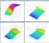
Once you breach into the mOHM range, the resistant heating is minimal. The over-voltage clamp is where most of the heat comes from at that point. I posted a really hacked page about it here with some QUCS simulations that show the voltage and current wave forms. From these wave forms you can look for the area under the curve to find the power that's being dissipated by different components. http://code.google.com/p/daecu/wiki/Injector_driver_theory I would caution about that package, if you cycle it though an automotive temperature range you'll likely find it fails. Or perhaps they made the chip have a similar expansion rate as the PCB, I'm not sure, however they are usually on a silicone wafer, so probably a blah expansion rate.
Wait a minute, that's not even clamped. That's just a generic diode. It would follow the curves at the top of the wiki page, and the heat would be dissipated in the injector not in the PCB. I don't recommend that kind of kick back mechanism, as noted on the wiki.
Wait a minute, that's not even clamped. That's just a generic diode. It would follow the curves at the top of the wiki page, and the heat would be dissipated in the injector not in the PCB. I don't recommend that kind of kick back mechanism, as noted on the wiki.
Welcome to the friendlier side of internet crazy
-
blundar
- contributor
- Posts: 141
- Joined: Tue Jan 07, 2014 4:38 am
- Location: Cincinnati, Ohio
- Github Username: blundar
- Slack: Dave B.
- Contact:
Re: Vishay SIS414dn low side switch
kb1gtt, do you do skype or gchat? I'd like to chat more about the contents of that wiki page. Every single OE ECU and standalone that I've ever had apart uses the diode/through injector method of dissipating. The method you put on the wiki sounds interesting, but the concern over long term exposure to high voltages is of a concern. Or do you want to just split a thread off here to discuss?
-Dave
-Dave
-
blundar
- contributor
- Posts: 141
- Joined: Tue Jan 07, 2014 4:38 am
- Location: Cincinnati, Ohio
- Github Username: blundar
- Slack: Dave B.
- Contact:
Re: Vishay SIS414dn low side switch
after talking with kb1gtt, I'll concede that there are good reasons to use a protected MOSFET and this is something that should be explored. They're simultaneously very easy and very hard to find. All the majors (ST, ON Semi, Infineon, Vishay, ... ... ) seem to have decent parts. Once there are some decisions about what needs to be implemented, it seems like there will be no trouble finding quality automotive grade parts.
-
abecedarian
- Posts: 386
- Joined: Fri Nov 15, 2013 10:49 am
Re: Vishay SIS414dn low side switch
There is a point of demarcation between what works and what's necessary.
If this remains a 'hobby' type of thing, what works is all you need; if a commercial product might be involved, obligations are significant.
Don't get me wrong, I think setting the bar high at the onset forces everyone else to take notice of what the little guys are doing (no offense anyone).
And if the engineering is there in force, at the beginning, costs are known... and things are less likely to break.
You can lead the horticulture but you can't make them think.