Power supply possible suggetion?

Hardware inside and outside of the ECU
Post Reply
User avatar
abecedarian
Posts: 386
Joined: Fri Nov 15, 2013 10:49 am

Power supply possible suggetion?

Post by abecedarian »

PS.jpg
PS.jpg (46.61 KiB) Viewed 15694 times
No filtering on the input, but reverse voltage protected, with LED indicators to show it. ;)

Comments?

Long story short, the p-channel mosfet won't conduct, and therefore won't connect the down-stream devices to power, if power is reversed.
Last edited by abecedarian on Mon Jan 27, 2014 9:01 pm, edited 2 times in total.
You can lead the horticulture but you can't make them think.
puff
contributor
contributor
Posts: 2961
Joined: Mon Nov 11, 2013 11:28 am
Location: Moskau

Re: Possible power interface?

Post by puff »

They say, automotive applications demand that there is a small coil in the power supply circuits to protect from voltage spikes.
Although, I haven't read data sheets on those tiny regulators.
I've just read - there is no mentioning of automotive use.
Read this!
http://www.maximintegrated.com/app-notes/index.mvp/id/4213

This is from Linear:
http://www.linear.com/solutions/1788
User avatar
abecedarian
Posts: 386
Joined: Fri Nov 15, 2013 10:49 am

Re: Possible power interface?

Post by abecedarian »


There are "load dump" situations that can occur for instance when jump starting a vehicle from another and the jumper cables are removed. That puts a sudden load on the alternator of the vehicle with the dead battery and can cause both under and over voltage conditions within a few milliseconds.

I didn't address that directly with what I posted, but the LDO's can operate with an input voltage 1.5v above their rated output, and can be stressed to over 15v input voltage for short periods of time; the diode/resistor following the mosfet should limit the voltage output as well, keeping it under 15v.
You can lead the horticulture but you can't make them think.
puff
contributor
contributor
Posts: 2961
Joined: Mon Nov 11, 2013 11:28 am
Location: Moskau

Re: Possible power interface?

Post by puff »

First of all, one needs to calculate, how much power we finally need (under cranking conditions?) - for the ECU itself, for signaling ignition coils, for injector driver circuits, for the sensor circuits. All of them draw some power, and when we sum it up, the final figure could be quite surprising…
I don't have a scope, but I have heard of spikes up to 150V in the car - will that LM1117 cope with those spikes?
At last, I'd like to learn beforehand, what happens to that chip when there's such a spike, or when we short its output (e.g., some accidental short circuit in the ECU) - will it open the circuit, or it will close the circuit and put the input 12V voltage just to the board? (I guess this requires some tests? :-)))
User avatar
abecedarian
Posts: 386
Joined: Fri Nov 15, 2013 10:49 am

Re: Possible power interface?

Post by abecedarian »

I understand completely what you're saying.
What I put up was a suggestion, and nothing more.

LM1117's generally go "poof" and nothing output when they go. I would hope the caps on the one side would absorb most of a spike, and give the diode / resistor on the output of the mosfet enough time to discharge excess voltage.

It wouldn't be too difficult though to add another diode, or maybe even mosfet, to dump over-voltage to ground.
You can lead the horticulture but you can't make them think.
User avatar
kb1gtt
contributor
contributor
Posts: 3758
Joined: Tue Sep 10, 2013 1:42 am
Location: ME of USA

Re: Power supply - abecedarian

Post by kb1gtt »

ISO spec for load dumps and such can be found in a link from this thread http://rusefi.com/forum/viewtopic.php?f=4&t=199&start=14

We need to know the load and load conditions to make better comments. However I would wonder why you are looking to remove the diode to gain some efficiency with the reverse polarity protection, but are ignoring the linears efficiency. For easy math, I'll assume 1A. So the diode with about .7V drop would dissipate .7W. However the linear dropping from 13V to 3V at 1A will dissipate 10 watts, while delivering 3 watts of power. So about 30% efficient, which is blah.

Also you can get load dumping on the regulated side, so I'd suggest a small diode across the linear to prevent the output voltage from exceeding the input voltage, and transient TVS diodes to prevent front end spikes. The next issue I see is that it doesn't block ripple very well, so expect AC ripple from the 12V to be seen on the regulated side.
Welcome to the friendlier side of internet crazy :)
User avatar
abecedarian
Posts: 386
Joined: Fri Nov 15, 2013 10:49 am

Re: Power supply - abecedarian

Post by abecedarian »

kb1gtt wrote:ISO spec for load dumps and such can be found in a link from this thread http://rusefi.com/forum/viewtopic.php?f=4&t=199&start=14

We need to know the load and load conditions to make better comments. However I would wonder why you are looking to remove the diode to gain some efficiency with the reverse polarity protection, but are ignoring the linears efficiency. For easy math, I'll assume 1A. So the diode with about .7V drop would dissipate .7W. However the linear dropping from 13V to 3V at 1A will dissipate 10 watts, while delivering 3 watts of power. So about 30% efficient, which is blah.

Also you can get load dumping on the regulated side, so I'd suggest a small diode across the linear to prevent the output voltage from exceeding the input voltage, and transient TVS diodes to prevent front end spikes. The next issue I see is that it doesn't block ripple very well, so expect AC ripple from the 12V to be seen on the regulated side.
Using LDO's was suggested since my motorcycle has a permanent magnet 3-phase generator and the regulator shunts excess current to ground via SCR's. If I were being 'jump started', the regulator would already by dumping current the bike doesn't need to ground on its own.

Anyhow.... Pulled a few schematics for switching supplies instead of linear and am looking at two: one with better than 85% efficiency for 3v3 output and the other with better than 90% efficiency for 5v0 output, each based on 7v to 18v input, and each sourcing around 1.5 Amperes. I think that's more than my bike needs. And oddly, neither requires "clamping" diodes.

I'll post more about it when I have schematics laid out.
You can lead the horticulture but you can't make them think.
User avatar
abecedarian
Posts: 386
Joined: Fri Nov 15, 2013 10:49 am

Re: Power supply possible suggetion?

Post by abecedarian »

A couple suggestions given to me*:

It is purportedly >80% efficient with 1A current draw at 3v3. I checked and the BOM for this is ~$4 USD, board not included.
PS3v3.jpg
PS3v3.jpg (76.17 KiB) Viewed 15631 times

The 5v0 variant is over 90% efficient, again purportedly. BOM is ~$3 USD, without the board.
PS5v0.jpg
PS5v0.jpg (49.83 KiB) Viewed 15631 times
Probably should make the observation that the BOM cost is probably based on quantity purchases too. :oops:

*note that the regulators shown are automotive qualified, but components listed may not be, and there is no reverse connection protection nor load dump considerations.
You can lead the horticulture but you can't make them think.
User avatar
abecedarian
Posts: 386
Joined: Fri Nov 15, 2013 10:49 am

Re: Power supply possible suggetion?

Post by abecedarian »

TPS54360 might be an option too...:
The TPS54360 is a 60 V, 3.5 A, step down regulator with an integrated high side MOSFET. The device survives
load dump pulses up to 65V per ISO 7637.
You can lead the horticulture but you can't make them think.
puff
contributor
contributor
Posts: 2961
Joined: Mon Nov 11, 2013 11:28 am
Location: Moskau

Re: Power supply possible suggetion?

Post by puff »

after the device is ready and assembled, I suggest the following testing procedure. for the testing purposes one would need at least the following equipment: the two channel scope and a dummy load
1. Connect this new power supply unit (PSU) to the old car with preferably malfunctioning voltage regulator and battery.
2. Connect the scope to the battery posts and to the output of the PSU. Start logging.
3. Switch on the starter.
turn off the car
connect dummy load, say, at 1Amp (needs further clarification and calculation - what circuits -will be used in our MCU)
repeat the procedure.
switch on all electric motors in the car (fan, AC, etc), start blinking with light, watching the scope.
finally, increase the load to the max value, simulating short circuit. if the converter is permanently dead - replace it with the new one and repeat at least three times (to make sure that during these incidents the 12V don't come to the 3.3 power rail)
User avatar
AndreyB
Site Admin
Posts: 14327
Joined: Wed Aug 28, 2013 1:28 am
Location: Jersey City
Github Username: rusefillc
Slack: Andrey B

Re: Power supply possible suggetion?

Post by AndreyB »

Is anyone interested in drawing the actual board, ideally in KiCad? @?
Very limited telepathic abilities - please post logs & tunes where appropriate - http://rusefi.com/s/questions

Always looking for C/C++/Java/PHP developers! Please help us see https://rusefi.com/s/howtocontribute
User avatar
abecedarian
Posts: 386
Joined: Fri Nov 15, 2013 10:49 am

Re: Power supply possible suggetion?

Post by abecedarian »

russian wrote:Is anyone interested in drawing the actual board, ideally in KiCad? @?
Would like to help but I use Eagle, not to mention I'm stumbling upon these parts for my project. That's why I titled the topic "possible suggestion", sharing what I'm finding, for you to consider for your project.

The last chip I posted is something I'm seriously considering using: I thought its 'load dump' rating and such might perk some ears and might be of use, if not simply because the chip is designed with load dump in mind, and since that's been mentioned here I thought I'd share.

Don't remember if I mentioned it before but 'load dump' isn't much of a problem for me since my bike is using a permanent magnet alternator, so it's not likely field windings will be over-excited and cause over-voltage conditions since I have no field windings. ;)
You can lead the horticulture but you can't make them think.
User avatar
abecedarian
Posts: 386
Joined: Fri Nov 15, 2013 10:49 am

Re: Power supply possible suggetion?

Post by abecedarian »

Well, anyhow....

If you don't have an account at www.ti.com you should. You can use Webench to spec out generalized power supplies like the 3v3/2A supply in the attached PDF.

I'd like to hear Jared's criticism of this, to see how accurate the web-based tool is.
I'm uploading a 12v nominal (7-18v) supply that should output 3v3/1A (2A peak) with > 80% efficiency (>90 @ 1A out).
The tool predicts some things and provides graphs in the attached file. It also creates a BOM so might be useful.
Attachments
3v3 Supply Basic.pdf
(122.41 KiB) Downloaded 358 times
You can lead the horticulture but you can't make them think.
User avatar
abecedarian
Posts: 386
Joined: Fri Nov 15, 2013 10:49 am

Re: Power supply possible suggetion?

Post by abecedarian »

Here's another, but 5v0 / 2A.
Attachments
5v0.pdf
(122.61 KiB) Downloaded 594 times
You can lead the horticulture but you can't make them think.
User avatar
kb1gtt
contributor
contributor
Posts: 3758
Joined: Tue Sep 10, 2013 1:42 am
Location: ME of USA

Re: Power supply possible suggetion?

Post by kb1gtt »

I've been meaning to reply, but time and resources = blah. Here's a quick one.

I see a 7V min, I think that needs to be closer to 5V. On the 5634 IO board I used the MAX5093B which does both buck and boost. It can go down to about 4V and up around 70V. It also has a ripple free output and will buck and boost, so you can get 5V with a 4V input. The down sides is that it can only do about .25 amps. Also there was a minor issue with the one I did on the IO board, one of the caps really needed to be a lower ESR. The cap would get a bit warm.

Here's a note about the voltage dip during cold cranking. http://www.maximintegrated.com/app-notes/index.mvp/id/4240

So I'd like to suggest we plan for the battery to dip to 5V for 40mS.

How does this compare to that $12 pre-made board? To me it seems almost the same. I might encourage using that other chip as it's got a good supply chain, and you can buy boards that are mostly done for very low dollar. The board I drafted in KICAD was a bit expensive, but what do you expect for low qty. I'd have to check how it does when people dump there load on it.

I don't expect much of a load dump issue caused by the alternator. I would expect the internal field winding would make the alternator a bit sluggish to respond to a change in load, which wold be well buffered by the battery. I generally expect load dumping to be similar to water hammer in a plumbing. Basically when you open a relay or something similar, you can get spikes and dips of voltage until things settle out a bit. Remember that when you have couple amps of current flowing, you can create a magnetic field that will need to decay, which is often where the energy is stored that causes the spikes and such.

I'm also a bit concerned wit the 700kHz switching frequency. If we are looking for beyond DIY, EMC requirements push you to have low emissions above 100kHz. Switching high power and high frequency can cause some odd RF issues. So you'll have to be careful about the layout, and items that can get close to this circuit physically. I might encourage a lower switching frequency

I think you will generally be best off with a pre-regulator setup.
Welcome to the friendlier side of internet crazy :)
User avatar
abecedarian
Posts: 386
Joined: Fri Nov 15, 2013 10:49 am

Re: Power supply possible suggetion?

Post by abecedarian »

, I spec'd 7v minimum in the design tools. That was chosen for a reason.

Cranking voltage can dip down below 8v, and in particular is apt to occur with a moderately discharged battery trying to start a high compression engine which will be drawing a lot of current for the starter motor.

My experience, as a once certified Detroit Diesel engine mechanic, is that when the voltage drops below 2/3 the system's rated voltage during cranking, it's time to give up the ghost: RPM while cranking will not be sufficient to start the engine... i.e. if the system voltage is 12 volts, when the voltage while cranking is under 8 volts, you most likely won't get the engine started. And this is with a 2-stroke diesel engine, not a 4-stroke engine, which gives extra time for any 'heat from compression' to dissipate into the engine block.

Keeping the ECU running when there's no chance of the engine starting is a waste.


*edit- Several 'semi' truck makers have been using hybrid 12/24 volt systems where they would have 2 pairs of 12v batteries. During cranking, solenoids would put them in series and raise the cranking voltage to 24v, but otherwise would have them in parallel, or maybe even completely isolated, to provide 12v for the 'comfort' items like TV and such when at the stop.
You can lead the horticulture but you can't make them think.
User avatar
kb1gtt
contributor
contributor
Posts: 3758
Joined: Tue Sep 10, 2013 1:42 am
Location: ME of USA

Re: Power supply possible suggetion?

Post by kb1gtt »

It's my understanding the 5V for 40mS spec, is mostly caused by battery chemistry. Basically when you start cranking, the rapid change in load takes a fraction of a second to get the chemical reaction happening. It can happen with a new/good battery, and will happen more often with a deep cycle battery in cold weather. Commonly batteries are made with that lead foil, which acts similar to a capacitor. This also can cause the battery be slightly sluggish as the foil being pack close together changes how the acid from circulates around the electrode.
Welcome to the friendlier side of internet crazy :)
User avatar
abecedarian
Posts: 386
Joined: Fri Nov 15, 2013 10:49 am

Re: Power supply possible suggetion?

Post by abecedarian »

kb1gtt wrote:It's my understanding the 5V for 40mS spec, is mostly caused by battery chemistry. Basically when you start cranking, the rapid change in load takes a fraction of a second to get the chemical reaction happening. It can happen with a new/good battery, and will happen more often with a deep cycle battery in cold weather. Commonly batteries are made with that lead foil, which acts similar to a capacitor. This also can cause the battery be slightly sluggish as the foil being pack close together changes how the acid from circulates around the electrode.
Besides the fact I have no idea exactly what you're talking about or referencing since you choose to post things without quotations or other things... 40 mS?
So now you want to 'de-bounce' the ignition switch on a car?

I give up.
You can lead the horticulture but you can't make them think.
User avatar
kb1gtt
contributor
contributor
Posts: 3758
Joined: Tue Sep 10, 2013 1:42 am
Location: ME of USA

Re: Power supply possible suggetion?

Post by kb1gtt »

In the above maximintegrated URL it shows this graphic.
Image
I'm recommending the 40mS and 5V thing because of their recommendation.

Also yes this applies to both ignition and injection current draws. I know someone who in a pinch during a camping trip tried to use the camper deep cell 12V battery as the truck battery instead of the car battery that went dead because they forgot to close a door or something like that. The battery would crank the engine, but it wouldn't start. They eventually found someone who gave them a jump start, and had jumper cables. The camper battery was new, however deep cycle instead of automotive. Basically during cranking the voltage dips were to low, either for the ECU, or for the spark / injection events.
Welcome to the friendlier side of internet crazy :)
User avatar
abecedarian
Posts: 386
Joined: Fri Nov 15, 2013 10:49 am

Re: Power supply possible suggetion?

Post by abecedarian »

I suppose that's plausible though I've started, on numerous occasions, a 7.3L Navistar diesel (used in Ford trucks) using an Interstate group 24 deep cycle battery without issues. It was the boss' truck when I worked building RVs.

A suitable cap on the input to the regulator should smooth and compensate for such voltage drops though.
You can lead the horticulture but you can't make them think.
User avatar
abecedarian
Posts: 386
Joined: Fri Nov 15, 2013 10:49 am

Re: Power supply possible suggetion?

Post by abecedarian »

kb1gtt wrote:I've been meaning to reply, but time and resources = blah. Here's a quick one.

I see a 7V min, I think that needs to be closer to 5V. On the 5634 IO board I used the MAX5093B which does both buck and boost. It can go down to about 4V and up around 70V. It also has a ripple free output and will buck and boost, so you can get 5V with a 4V input. The down sides is that it can only do about .25 amps. Also there was a minor issue with the one I did on the IO board, one of the caps really needed to be a lower ESR. The cap would get a bit warm.

Here's a note about the voltage dip during cold cranking. http://www.maximintegrated.com/app-notes/index.mvp/id/4240

So I'd like to suggest we plan for the battery to dip to 5V for 40mS.
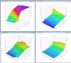
I think I forgot to mention these, set for 6-18v in, 2.0A out and 60v input transient tolerable. They require 6 volt to start, but low-dropout is around 4.3v.
Attachments
3v3_V2.pdf
(100.75 KiB) Downloaded 500 times
5v0.pdf
(101.86 KiB) Downloaded 510 times
You can lead the horticulture but you can't make them think.
User avatar
kb1gtt
contributor
contributor
Posts: 3758
Joined: Tue Sep 10, 2013 1:42 am
Location: ME of USA

Re: Power supply possible suggetion?

Post by kb1gtt »

Does the simulation predict the ripple? It looks like the ripple for 5V would be around 25mV. is that correct or realistic?
Welcome to the friendlier side of internet crazy :)
Post Reply