What's the total cost of that connector? Most of these are around $1 per connection. That's a pro-rated cost for the shell, cost for the pins on both sides. Which is commonly $100 for the connector.
There are some options from china which are much lower cost, they include pig tails.
Re: let's choose an enclosure
Posted: Wed Dec 28, 2016 4:20 pm
by AndreyB
stefanst wrote:90s Honda Accord boxes are the cheapest on Ebay
Also about 30% extra real estate. If a honda box board is ever created I would be begging for no 'native' chip option but 2 layer.
Re: let's choose an enclosure
Posted: Sun Mar 12, 2017 5:56 pm
by AndreyB
Another packaging approach - separate connector pcb and separate ECU pcb, with only wires between.
Sorry for offtopic. Does anyone know partnumber of this yellow connector? Seems it the same as subaru used for their early imprezas and legacy bg.
Re: let's choose an enclosure
Posted: Wed Apr 05, 2017 12:30 pm
by AndreyB
Dron_Gus wrote:
Sorry for offtopic. Does anyone know partnumber of this yellow connector? Seems it the same as subaru used for their early imprezas and legacy bg.
Thanks. I should be more attentive. Already bought several from e-bay. Better than unsoldering from dead ecu.
Re: let's choose an enclosure
Posted: Thu Apr 06, 2017 3:16 am
by puff
$24 shipped from eBay? probably not that bad %-)
what about the mating part? and which enclosure is it compatible with? (it would be handy to have all that stuff on the wiki page)
Re: let's choose an enclosure
Posted: Thu Apr 06, 2017 6:41 am
by Dron_Gus
puff wrote:$24 shipped from eBay? probably not that bad %-)
what about the mating part? and which enclosure is it compatible with? (it would be handy to have all that stuff on the wiki page)
I'm building RusEFI for exact car, so I have all mating parts in car.
Enclosure also from stock subaru ECU like 22611AA810 and many others from early 90's imprezas, foresters, legacys/libertys and so on.
I can update WiKi with at least Impreza JDM and EDM ECU's pinouts and connection diagrams. It was hard to find so it can be also useful for someone outside RusEFI project to.
Re: let's choose an enclosure
Posted: Thu Apr 06, 2017 8:20 am
by puff
lucky you are! not sure if a used mating connector, cut off from a crashed vehicle, would be of any use - extending all these wires doesn't seem to be a good idea..
Re: let's choose an enclosure
Posted: Thu Apr 06, 2017 9:20 am
by Dron_Gus
puff wrote:lucky you are! not sure if a used mating connector, cut off from a crashed vehicle, would be of any use - extending all these wires doesn't seem to be a good idea..
Mating parts are available at Mouser. Just need to dig some documentation about exact part numbers. http://www.te.com/commerce/DocumentDelivery/DDEController?Action=showdoc&DocId=Specification+Or+Standard%7F108-5280%7FF6%7Fpdf%7FJapanese%7FJPN_SS_108-5280_F6.pdf%7F3-178780-6
Looks like mate parts are
26 pins (10 hi-current + 16 low-current) 174516-6
16 pins (all low current) 174514-6
12 pins (all low current) 174913-1
22 pins (6 hi-current + 16 low-current) 174515-6
And terminals 173716-1 or 173716-2 and 173630-1 or 173630-2
All of them are available at Mouser (not sure if it is easy to order to Russia, but I'll try)
So only one problem is PCB connector - 178780-6 - currently available only on eBay from one seller.
Re: let's choose an enclosure
Posted: Thu Apr 06, 2017 1:48 pm
by AndreyB
Dron_Gus wrote:So only one problem is PCB connector - 178780-6 - currently available only on eBay from one seller.
I believe this guy sells "old new stock" so once he sells all he has it's over. On the other hand it's easy to remove from a used ECU with a torch.
$24 for a pcb side seems okay. but I guess, the mating part would cost way too much if I order it from Mouser. They are not cheap themselves, plus the cost of delivery makes it not feasible...
Re: let's choose an enclosure
Posted: Thu Apr 06, 2017 3:17 pm
by AndreyB
puff wrote:They are not cheap themselves, plus the cost of delivery makes it not feasible...
That's why I enjoy used Honda/Mazda/Toyota connectors
Re: let's choose an enclosure
Posted: Thu Apr 06, 2017 3:35 pm
by matt
look like same with subaru connector, but part number not match.
puff wrote:$24 for a pcb side seems okay. but I guess, the mating part would cost way too much if I order it from Mouser. They are not cheap themselves, plus the cost of delivery makes it not feasible...
I ordered 5 sets of mating connectors + termonals. Total is about $90. Let's see if they accept my order. (They redirect my order to some representative in Saint-P.)
Re: let's choose an enclosure
Posted: Fri Apr 07, 2017 12:11 am
by mobyfab
Often with multilock/molex you have different part numbers for the same connector based on random things like plating so there might be 3-4 compatible references for that one.
Also in this case the pictures are from a civic and a lancer evo, not a subaru. (yellow connector)
Re: let's choose an enclosure
Posted: Sun Apr 09, 2017 7:10 pm
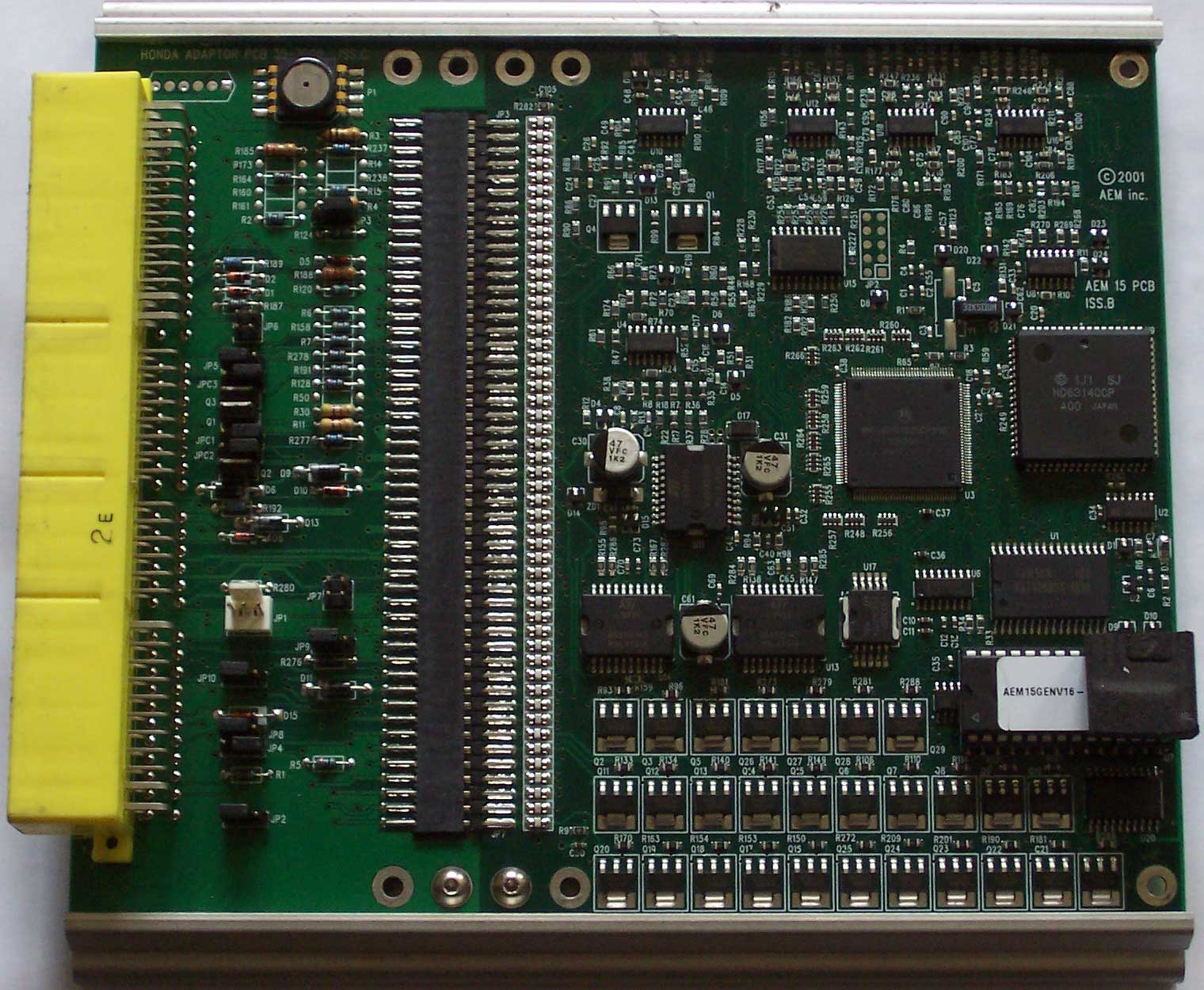
by kb1gtt
In the above pictures, it shows an AEM ECU which uses a replaceable ECU connector. Right now Frankenso allows you to re-map your pin out by using a pile of jumper wires in the W## area of the PCB. As well the ECU connector is set to a particular ECU connector. It would be handy to have an adapter area similar to the AEM ECU such that we can swap out this connection with the real world. I don't like the 0.1inch spaced headers for power circuits, as there are many issues caused by the contact resistance of these connectors. I know the devices like the below exist, but they are very pricey and quite bulky.
DIN 41612?
Molex has some options for power as well.
Re: let's choose an enclosure
Posted: Sun Apr 09, 2017 11:34 pm
by Abricos
same connector and adapter?
Re: let's choose an enclosure
Posted: Mon Apr 10, 2017 12:23 am
by kb1gtt
I kind of like the adapter harness, but I fear a need to make changes in the field, which wold want crimp tools, quality control, ect.
I think a board does not need to be hot-swap-able. Also I'm not crazy about small contacts carrying large currents, especially when they are inductive currents. The small ohms of the connector cause some funky tank circuits. I'm tempted to think it should be a soldered option to ensure minimal connection resistance.
a resistor is about 3mm in diameter, 4mm to be safe, We would only fit 40 of these on the width of the board - not enough. We need at least a 2 row connector / wiring approach.
So the 0.1 inch header is rated at 3A and you say you do not like combining multiple pins to share load? how much current do we want on the most loaded super GND pin?
Re: let's choose an enclosure
Posted: Mon Apr 10, 2017 8:55 am
by mobyfab
I still think pin headers would work fine as long as you share the load.
If AEM still does it, it must be working fine, they've been doing this for 20+ years.
This is the current design for their EMS V2: (found on a supra forum)
Note that they have coil drivers (so 10A+ ) directly on the "adapter" board but their other outputs (~3A) on the motherboard.
Re: let's choose an enclosure
Posted: Mon Apr 10, 2017 10:36 am
by kb1gtt
You can install every other resistor, then install the remaining resistors such that you stagger the resistors. AKA some touch the PCB others are stacked on top of the resistors that are touching the PCB. The key issue I see with this is the assembly labor. That will likely be more costly than what ever jumper device is chosen.
I don't know the exact layout of that picture, but it appears they put the sensitive high impedance analog between the high speed digital and high frequency power switch mode power supply. It appears that unintentional radiators are likely to couple into the analog circuits on that PCB. Also that pile of apparent power transistors is likely a bit weak in thermal design. Even if each of those transistors are only making a like 1mW of energy, those devices in the middle of the pack are likely to get really hot. If they added some thermal via's it would allow the entire array of components to get much hotter before you ran into issues. I'm not particular impressed with that layout, but perhaps I'm just being too critical. Perhaps my concerns are overly conservative from the design standpoint.