Page 1 of 1
HOWTO connect LCD 16x2
Posted: Thu Feb 20, 2014 11:15 pm
by Kot_dnz
We have standard low cost 16x2 LCD display based on HD44780.

Ebay cost 3.83 USD
http://www.ebay.com/itm/1pcs-1602-16x2-HD44780-Character-LCD-Display-Module-LCM-blue-blacklight-New-/251049844026?pt=LH_DefaultDomain_0&hash=item3a73bc9d3a
With according datasheet
http://www.openhacks.com/uploadsproductos/eone-1602a1.pdf display Power Supply is 5V.
Input High voltage 2,2v allow us send datas 3.3v directly to data pins DB4-DB7.
In our system we use 4-bit mode.
Depend of power of your USB port you can connect Vcc & GND:
- or directly to DISCOVERY
or via external supply 5v (in this case Vcc -> external +5v, GND -> LCD GND + -> DISCOVERY GND)
In any case all GND must be connected and have same level!
Working system on final:

General troubleshooting:
1. You can start with connection only first 3 pins and adjust Contrast via 10KOhm adjusted resistor. After see full first string of bars connect others.
2. Adjusted resistor i connect one pin to +5v, second to contrast, third to GND.
3. Some display do not have Back LEDs.
4. With external +5v on RESET some times require reset LCD before reset board.
5. pin #5 - R/W pin - should be connected to GND. So, there should be
three GND pins and two +5 pins.
Hope this enough.
P.S. This display can be upgrade by IIC/I2C/TWI/SPI Serial Interface Board Module Port for Arduino 1602LCD Display
http://www.ebay.com/itm/IIC-I2C-TWI-SPI-Serial-Interface-Board-Module-Port-for-Arduino-1602LCD-Display-/141146290709?pt=LH_DefaultDomain_0&hash=item20dcf97a15
Re: HOWTO connect LCD 16x2
Posted: Thu Feb 20, 2014 11:28 pm
by AndreyB
I've updated the
pinout document

And my 20x4 has exactly the same pinout
Re: HOWTO connect LCD 16x2
Posted: Mon Mar 03, 2014 7:49 pm
by puff
so just six wires needed (including power)?
what does the firmware (current version) display on this screen?
i'll probably give it a try in the end of this month...
Re: HOWTO connect LCD 16x2
Posted: Mon Mar 10, 2014 2:47 am
by AndreyB
The pinout has changed to accommodate Frankenstein board, I've just updated the table in the previous post.
Re: HOWTO connect LCD 16x2
Posted: Tue Mar 25, 2014 9:34 pm
by puff
argh! broken images!
Re: HOWTO connect LCD 16x2
Posted: Wed Mar 26, 2014 2:18 am
by AndreyB
I use a 2K resistor between GND and 3rd pin for contrast
Re: HOWTO connect LCD 16x2
Posted: Wed Mar 26, 2014 5:32 am
by rus084
I use a 4,7K pot to control contrast.
я думаю что нужно иногда экран полностью перерисовывать - у меня от помех некоторые символы иногда чтото нето показывают
Re: HOWTO connect LCD 16x2
Posted: Wed Mar 26, 2014 7:17 pm
by AndreyB
puff, can you please translate your messages to English and stop posting questions in Russian?

Re: HOWTO connect LCD 16x2
Posted: Wed Mar 26, 2014 7:29 pm
by puff
should it be working right out of the box, without any tinkering with firmware? The thing is my 2x16 panel shows only the upper raw of 16 black fields. With 1K resistor between the third pin and ground it's somewhat faded, with 2K it's hardly visible, when I short the third pin directly to the ground, it's solid black.
I rechecked connections, it seems everything is connected correctly. What could go wrong?
Re: HOWTO connect LCD 16x2
Posted: Wed Mar 26, 2014 7:34 pm
by AndreyB
1) try resetting the firmware coupe of times (black button) - the LED code has known reliability issues
2) it is really weird with the contrast resistor - a very narrow range of resistance gives you visible characters. Any chance you can try this with a potentiometer?
so, 3 GND pins. 2 VCC pins. 6 signal wires - validate the pinout with
https://svn.code.sf.net/p/rusefi/code/trunk/firmware/config/boards/arro_board.h
external power supply - I believe one USB is not enough.
Re: HOWTO connect LCD 16x2
Posted: Wed Mar 26, 2014 7:46 pm
by puff
should I power up just the backlight from external power supply? or both of them?
rus084, with shorted pin I get the upper row black, and the lower row faded. no symbols.
where should I find that 10-20K pot?
I rechecked the pinout - it's the same as in this excel file.
Re: HOWTO connect LCD 16x2
Posted: Wed Mar 26, 2014 8:55 pm
by puff
okay. tried external power supply for the first two pins, then for the last two pins (common ground both cases), pot, changing black squares from dark black to almost invisible, and still, blank screen…

Re: HOWTO connect LCD 16x2
Posted: Wed Mar 26, 2014 9:17 pm
by AndreyB
time for a picture
show us all your wires where they are connected to the screen
Re: HOWTO connect LCD 16x2
Posted: Wed Mar 26, 2014 9:36 pm
by Kot_dnz
puff wrote:okay. tried external power supply for the first two pins, then for the last two pins (common ground both cases), pot, changing black squares from dark black to almost invisible, and still, blank screen…
please attention - ground must be the same for both supply
Re: HOWTO connect LCD 16x2
Posted: Wed Mar 26, 2014 10:12 pm
by puff
here's what I see in logic analyzer (probably that's what should be there):
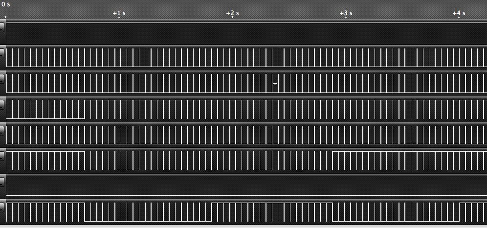
- Снимок экрана 2014-03-27 в 2.10.45.png (49.08 KiB) Viewed 20662 times

- Снимок экрана 2014-03-27 в 2.11.13.png (35.25 KiB) Viewed 20662 times
Re: HOWTO connect LCD 16x2
Posted: Wed Mar 26, 2014 10:15 pm
by puff
fourth channel - these spikes in the second picture are just 2µs, that's right?
Re: HOWTO connect LCD 16x2
Posted: Wed Mar 26, 2014 10:22 pm
by puff
just blew up the pot

it smells ugly when burning up
Re: HOWTO connect LCD 16x2
Posted: Thu Mar 27, 2014 12:57 am
by AndreyB
So, a picture of your wires...
Re: HOWTO connect LCD 16x2
Posted: Thu Mar 27, 2014 6:12 am
by rus084
I have everything worked from one usb port, but the contrast was too weak. because the Chinese mini usb cable has too much resistance.
I took the adapter usb-wire connector to the computer, and connect the wire to the +5 volt line Discovery. so worked perfectly
Re: HOWTO connect LCD 16x2
Posted: Thu Mar 27, 2014 7:05 pm
by puff
here are the wires:

- IMG_20140327_225335_1.jpg (641.39 KiB) Viewed 20655 times

- IMG_20140327_225255_1.jpg (603.77 KiB) Viewed 20655 times

- IMG_20140327_225150_1.jpg (678.89 KiB) Viewed 20655 times
it turns out 'H' in the display model means wide temperature range, therefore it needs negative power supply. I used a mixed pack of NiCd and NiMh batteries for that purpose, which resulted in two distinct rows of black squares…
Re: HOWTO connect LCD 16x2
Posted: Thu Mar 27, 2014 7:14 pm
by AndreyB
Is the green wire used to ground pin #5, the R/W pin? I have it constantly ground.
Re: HOWTO connect LCD 16x2
Posted: Thu Mar 27, 2014 7:23 pm
by puff
fck! spent the whole evening yesterday! why didn't I find any instruction on connecting it to ground?


- IMG_20140327_232102.jpg (650.02 KiB) Viewed 20555 times
Re: HOWTO connect LCD 16x2
Posted: Thu Mar 27, 2014 7:28 pm
by AndreyB
russian wrote:so, 3 GND pins
We both see this on the first page, do we?
Also the datasheet says H for read L for write...
I will go make this more visible.
Re: HOWTO connect LCD 16x2
Posted: Thu Mar 27, 2014 7:46 pm
by puff
three grounds: power supply, backlight supply, contrast. who reads data sheets nowadays?
okay,
so, today we can't control this display from java console? I have to build firmware myself to make any use of it?
the date there is also quite strange)
could you make it start counting from the built time?
Re: HOWTO connect LCD 16x2
Posted: Thu Mar 27, 2014 8:00 pm
by AndreyB
I am open to ideas on what should be displayed on this screen.
I have just changed it yesterday and it now shows CLT temperature together with current RPM, which does not really fit on your 16x2 because I am developing it for my 20x4.
The time was only needed for troubleshooting, it's not really needed any more.
I will probably add warning error code or error message display soon, and for now the main purpose is displaying fatal error messages.
Re: HOWTO connect LCD 16x2
Posted: Thu Mar 27, 2014 8:09 pm
by rus084
i thing , needed 74hc595 or look like adapter chip for pin economy
Re: HOWTO connect LCD 16x2
Posted: Thu Mar 27, 2014 8:35 pm
by puff
altogether six wires to discovery board, four wires - power, yet another two - 12 wires in total
so far there are plenty of pins available, and I don't think there would be any significant demands for more pins. at least I hope there will be four pins left for ignition signal pickup