Alternator field control circuit

Hardware inside and outside of the ECU
User avatar
AndreyB
Site Admin
Posts: 14323
Joined: Wed Aug 28, 2013 1:28 am
Location: Jersey City
Github Username: rusefillc
Slack: Andrey B

Alternator field control circuit

Post by AndreyB »

See http://rusefi.com/forum/viewtopic.php?f=5&t=1088 for software side of alternator control

How do you like this
The charging lamp will come on if either the inlet air temperature, coolant temperature, or vehicle speed sensor fail.
Exactly. inlet air temperature plays a role in OEM battery charging logic... Oh, and there is a battery temperature sensor.

Update:

Image
Very limited telepathic abilities - please post logs & tunes where appropriate - http://rusefi.com/s/questions

Always looking for C/C++/Java/PHP developers! Please help us see https://rusefi.com/s/howtocontribute
User avatar
AndreyB
Site Admin
Posts: 14323
Joined: Wed Aug 28, 2013 1:28 am
Location: Jersey City
Github Username: rusefillc
Slack: Andrey B

Re: Alternator field control circuit

Post by AndreyB »

I have tried and failed to control the alternator today.

Resistance between field wire and ground: 12 Ohm
Battery voltage, car not running: 12v. Voltage on the battery with stock OEM: 13.9-14.0 I guess that's the alternator doing the job

Now, rusEfi. If I connect field wire directly to battery positive terminal I can see how the car RPMs go up (load goes up?) and the voltage goes from 12v to 16v.

On the more depressing note:

I have 400Hz PWM via the hi-side TC4427 chips. I've tried 60% (~7v), 80% and 95% (~11v) PWM connected to alternator wire to no avail - the alternator does not seem to engage.
Very limited telepathic abilities - please post logs & tunes where appropriate - http://rusefi.com/s/questions

Always looking for C/C++/Java/PHP developers! Please help us see https://rusefi.com/s/howtocontribute
puff
contributor
contributor
Posts: 2961
Joined: Mon Nov 11, 2013 11:28 am
Location: Moskau

Re: Alternator field control circuit

Post by puff »

I guess you need to learn how alternator works. I guess you need some rc circuit to at least smoothen that pwm. or increase its frequency may be. not sure if that is posible at all. suppose, there are 6 or 8 windings in that alternator. suppose,the ratio is 1:1. suppose.you idle at 900rpm. what would be the freuency of that alternaring current?
User avatar
AndreyB
Site Admin
Posts: 14323
Joined: Wed Aug 28, 2013 1:28 am
Location: Jersey City
Github Username: rusefillc
Slack: Andrey B

Re: Alternator field control circuit

Post by AndreyB »

Image

I guess this 100R is the reason the alternator is not happy. I am going to try with a 0R instead so that I can provide the alternator field wire with more current.
Very limited telepathic abilities - please post logs & tunes where appropriate - http://rusefi.com/s/questions

Always looking for C/C++/Java/PHP developers! Please help us see https://rusefi.com/s/howtocontribute
User avatar
kb1gtt
contributor
contributor
Posts: 3758
Joined: Tue Sep 10, 2013 1:42 am
Location: ME of USA

Re: Alternator field control circuit

Post by kb1gtt »

Remember the hi/low driver can only safely drive an average of.125 amps for a prolonged period of time at higher temperatures. With our currently colder weather you should be safe for more average current. Also if it does overheat, it should simply shut itself off. So if you find it drops out from time to time, it might be the internal thermal safeties kicking in.
Welcome to the friendlier side of internet crazy :)
User avatar
AndreyB
Site Admin
Posts: 14323
Joined: Wed Aug 28, 2013 1:28 am
Location: Jersey City
Github Username: rusefillc
Slack: Andrey B

Re: Alternator field control circuit

Post by AndreyB »

kb1gtt wrote:Remember the hi/low driver can only safely drive an average of.125 amps for a prolonged period of time at higher temperatures.
Oh, that's because 1.5A is just "Peak Output Current" I guess. Let's see if 0R would make alternator engage and go from there I guess. Since a direct connection to battery had bumped voltage to 16v and we only need 14v maybe we would only need something like 0.5A

One way or another we need a higher-amperage high-side control - remember how VTEC is another potential use case.
Very limited telepathic abilities - please post logs & tunes where appropriate - http://rusefi.com/s/questions

Always looking for C/C++/Java/PHP developers! Please help us see https://rusefi.com/s/howtocontribute
puff
contributor
contributor
Posts: 2961
Joined: Mon Nov 11, 2013 11:28 am
Location: Moskau

Re: Alternator field control circuit

Post by puff »

I might be mistaken, but when you pulled it up to the battery, it was content voltage. The huge resistor in the original setup also creates constant voltage. While with frankenso you get PWM - pulses. Basically, you are trying to drive a coil with PWM. Do you have a flyback diode? You could try to set it up to 100% and see if it rev up with voltage rising to 16v - that would prove my shady theory…
User avatar
AndreyB
Site Admin
Posts: 14323
Joined: Wed Aug 28, 2013 1:28 am
Location: Jersey City
Github Username: rusefillc
Slack: Andrey B

Re: Alternator field control circuit

Post by AndreyB »

the 400Hz is not random - it's coming from http://www.apra.org/News/Mohammad/Sammy_0712.pdf

As for diodes, you are forgetting about what it says in my signature below.
Very limited telepathic abilities - please post logs & tunes where appropriate - http://rusefi.com/s/questions

Always looking for C/C++/Java/PHP developers! Please help us see https://rusefi.com/s/howtocontribute
User avatar
rus084
contributor
contributor
Posts: 678
Joined: Sun Dec 01, 2013 1:40 pm
Location: Russia , Stavropol

Re: Alternator field control circuit

Post by rus084 »

You should use P-chanel mosfet
User avatar
kb1gtt
contributor
contributor
Posts: 3758
Joined: Tue Sep 10, 2013 1:42 am
Location: ME of USA

Re: Alternator field control circuit

Post by kb1gtt »

When idling and WOT'ish, can you insert a DMM in line and see what current flows when you use a wire to 12V? For all we know it's only drawing mA instead of large A's. For some reason I want to say 100:1 is a common field to output current ratio. We might be dealing with .6A for 60A output.
Welcome to the friendlier side of internet crazy :)
User avatar
AndreyB
Site Admin
Posts: 14323
Joined: Wed Aug 28, 2013 1:28 am
Location: Jersey City
Github Username: rusefillc
Slack: Andrey B

Re: Alternator field control circuit

Post by AndreyB »

kb1gtt wrote:When idling ... can you insert a DMM in line and see what current flows when you use a wire to 12V?
idling with rusEfi, +12V on battery => DMM => alternator field wire: 6.5A - engine is jerking up, probably charging. pretty large spark

idling with rusEfi, rusEfi control field control wire => DMM => alternator field wire: 0.5A - engine is maybe reacting a bit, not sure. the spark is pretty tiny. voltage on the battery does not change so I guess no charging
Very limited telepathic abilities - please post logs & tunes where appropriate - http://rusefi.com/s/questions

Always looking for C/C++/Java/PHP developers! Please help us see https://rusefi.com/s/howtocontribute
User avatar
AndreyB
Site Admin
Posts: 14323
Joined: Wed Aug 28, 2013 1:28 am
Location: Jersey City
Github Username: rusefillc
Slack: Andrey B

Re: Alternator field control circuit

Post by AndreyB »

PS: just a random though - that BTS2140 ignition chip, is is a P-channel MOSFET? any chance to use it for alternator field wire control as a temporary solution?
Very limited telepathic abilities - please post logs & tunes where appropriate - http://rusefi.com/s/questions

Always looking for C/C++/Java/PHP developers! Please help us see https://rusefi.com/s/howtocontribute
puff
contributor
contributor
Posts: 2961
Joined: Mon Nov 11, 2013 11:28 am
Location: Moskau

Re: Alternator field control circuit

Post by puff »

do the dmm readings change when you change duty cycles? have you considered putting a diode in parallel to the alternator (google flyback diode, jared, am i right?)
could it be so that the driver goes to sort of protection mode? besides that, the 400hz value is still not clear for me. have you tried 100% duty cycle trick?
User avatar
kb1gtt
contributor
contributor
Posts: 3758
Joined: Tue Sep 10, 2013 1:42 am
Location: ME of USA

Re: Alternator field control circuit

Post by kb1gtt »

The field winding is different than a solenoid or most inductive loads. I'm not sure if it wants a diode or not. There's a bunch of mutual inductance between the power winding's and the field winding's. A diode might cause problems, or it might help. Unfortunately I'm ignorant about typical alternator wiring, and it's many variants. I would need to research the interwebs for examples schematic and affiliated information.

I don't fully follow russians measurements. I think he's saying, dead short field to 12V via DMM was 6.5A on the field wire and it produced heavy charging. Then when PWM'ed by frank board to .5A it was not charging. I'm assuming you have a 60A alternator, so it appears the field is controlling around a 10:1 ratio. Do you know your alternators current rating? Can you get the frank board to do 1A.

Using a PMOSFET might be a bit risky, as they clamp to much higher voltage. Perhaps put a scope on it to see if your getting a kick back on the existing chip and PWM'ed wire. If there is not kick, we might not care if the clamping voltage it higher.
Welcome to the friendlier side of internet crazy :)
User avatar
rus084
contributor
contributor
Posts: 678
Joined: Sun Dec 01, 2013 1:40 pm
Location: Russia , Stavropol

Re: Alternator field control circuit

Post by rus084 »

russian wrote:PS: just a random though - that BTS2140 ignition chip, is is a P-channel MOSFET? any chance to use it for alternator field wire control as a temporary solution?
bts2140 is not a MOSFET it is n-chanel IGBT .

this is alternator wiring in russian's cars
Image
kb1gtt wrote:Using a PMOSFET might be a bit risky, as they clamp to much higher voltage.
for using p-mosfets is drivers . for example ir2101 (i use it in my injector driver)
User avatar
AndreyB
Site Admin
Posts: 14323
Joined: Wed Aug 28, 2013 1:28 am
Location: Jersey City
Github Username: rusefillc
Slack: Andrey B

Re: Alternator field control circuit

Post by AndreyB »

kb1gtt wrote:I don't fully follow russians measurements. I think he's saying, dead short field to 12V via DMM was 6.5A on the field wire and it produced heavy charging. Then when PWM'ed by frank board to .5A it was not charging.
Yes, that's exactly what is going on.
kb1gtt wrote: I'm assuming you have a 60A alternator, so it appears the field is controlling around a 10:1 ratio. Do you know your alternators current rating? Can you get the frank board to do 1A.
According to http://www.rockauto.com it's 85A
rus084 wrote:bts2140 is not a MOSFET it is n-chanel IGBT.
Ops, not an option then.

So, what's the plan?
Very limited telepathic abilities - please post logs & tunes where appropriate - http://rusefi.com/s/questions

Always looking for C/C++/Java/PHP developers! Please help us see https://rusefi.com/s/howtocontribute
puff
contributor
contributor
Posts: 2961
Joined: Mon Nov 11, 2013 11:28 am
Location: Moskau

Re: Alternator field control circuit

Post by puff »

the plan is you are trying to measure the current with a 100% duty cycle as if you shorten it to the battery? :) any chance the driver is malfunctioning?
User avatar
AndreyB
Site Admin
Posts: 14323
Joined: Wed Aug 28, 2013 1:28 am
Location: Jersey City
Github Username: rusefillc
Slack: Andrey B

Re: Alternator field control circuit

Post by AndreyB »

puff wrote:the plan is you are trying to measure the current with a 100% duty cycle as if you shorten it to the battery? :)
To be honest the code probably does not support 100% right now, but there should really be no difference between 95% and 100%, so we need a different plan :)

added a ticket for 100% pwm - https://sourceforge.net/p/rusefi/tickets/122/
Very limited telepathic abilities - please post logs & tunes where appropriate - http://rusefi.com/s/questions

Always looking for C/C++/Java/PHP developers! Please help us see https://rusefi.com/s/howtocontribute
puff
contributor
contributor
Posts: 2961
Joined: Mon Nov 11, 2013 11:28 am
Location: Moskau

Re: Alternator field control circuit

Post by puff »

okay. still, I didn't get how it was done in stock ecu, and why don't you want just mimic it?
User avatar
AndreyB
Site Admin
Posts: 14323
Joined: Wed Aug 28, 2013 1:28 am
Location: Jersey City
Github Username: rusefillc
Slack: Andrey B

Re: Alternator field control circuit

Post by AndreyB »

puff wrote:okay. still, I didn't get how it was done in stock ecu, and why don't you want just mimic it?
f@#$@#$asd me. MIMIC WHAT? Have you noticed how much silicone is on stock ECU, and how tiny components are on stock ECU? The pictures are somewhere in this thread. You want to trace the stock ECU with all this sticky crap on it or you want to disassemble stock ECU code? One way or another, be my guest and let us know what you find. It would help!
Very limited telepathic abilities - please post logs & tunes where appropriate - http://rusefi.com/s/questions

Always looking for C/C++/Java/PHP developers! Please help us see https://rusefi.com/s/howtocontribute
puff
contributor
contributor
Posts: 2961
Joined: Mon Nov 11, 2013 11:28 am
Location: Moskau

Re: Alternator field control circuit

Post by puff »

probably it's not that difficult connect o-scope to the field wire in stock setup?
User avatar
AndreyB
Site Admin
Posts: 14323
Joined: Wed Aug 28, 2013 1:28 am
Location: Jersey City
Github Username: rusefillc
Slack: Andrey B

Re: Alternator field control circuit

Post by AndreyB »

ST has purpose-build voltage regulator chips. The obsolete ST L9407 is available from China, the more current (?) one ST L9466 does not seem to be available.

Ideally I would love to use some DPAK mosfet on the ignition module breakout board we've made for DPAK
Very limited telepathic abilities - please post logs & tunes where appropriate - http://rusefi.com/s/questions

Always looking for C/C++/Java/PHP developers! Please help us see https://rusefi.com/s/howtocontribute
User avatar
AndreyB
Site Admin
Posts: 14323
Joined: Wed Aug 28, 2013 1:28 am
Location: Jersey City
Github Username: rusefillc
Slack: Andrey B

Re: Alternator field control circuit

Post by AndreyB »

How about FAIRCHILD FQB12P20TM P-CHANNEL MOSFET, -200V, -11.5A, D2PAK?
Very limited telepathic abilities - please post logs & tunes where appropriate - http://rusefi.com/s/questions

Always looking for C/C++/Java/PHP developers! Please help us see https://rusefi.com/s/howtocontribute
User avatar
rus084
contributor
contributor
Posts: 678
Joined: Sun Dec 01, 2013 1:40 pm
Location: Russia , Stavropol

Re: Alternator field control circuit

Post by rus084 »

this transistor will be closed if gate voltage =vbat and will be opening if voltage on gate < vbat - 3v .

You should use not logical transistor with -10v gate voltage .

I draw some schematic .
Attachments
alternator.png
alternator.png (17.46 KiB) Viewed 21603 times
Last edited by rus084 on Thu Dec 11, 2014 11:27 am, edited 2 times in total.
User avatar
kb1gtt
contributor
contributor
Posts: 3758
Joined: Tue Sep 10, 2013 1:42 am
Location: ME of USA

Re: Alternator field control circuit

Post by kb1gtt »

Thanks for the picture, I see green wire is even the same color. Is there a forum post or some additional details about this picture
Image
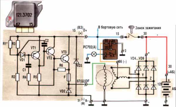
I wonder what VD3 is about. I see darling-ton pair transistors, with an analog bias current. The bias current from VT1, will turn on VT2 and VT3 controlling to 14.4V-ish. I wonder if the resistor values are know, or if the VD1 is known.

I agree with rus84's schematic for driving the P-MOSFET. I think with a PWM attempt, you'll need a much larger diode for the equivalent of VD2, as the PWM will spike that diode very often, while the analog version will only spike it on engine stop. It might be worth while to consider a transistor setup with PWM drive to analog current control. However that's going to make some heat. Hmmm, there has to be a better way.
Welcome to the friendlier side of internet crazy :)
User avatar
kb1gtt
contributor
contributor
Posts: 3758
Joined: Tue Sep 10, 2013 1:42 am
Location: ME of USA

Re: Alternator field control circuit

Post by kb1gtt »

How large of a cap do you have laying around? It would need or want to be like 18V rated or higher. See below modified pencil sketch. I added a 10k to 1k resistor on the left, and as large a reasonably possible cap on the output.
20141211_103323.jpg
20141211_103323.jpg (45.8 KiB) Viewed 21603 times
Basic theory is that the PWM will keep the cap charged up to say 6V, which would then conduct around 3A instead of the full 6.5A. This wold ease the stress on the fly back diode and would make your PWM into semi high efficiency semi analog current supply. However the cap size and Ton and Toff times of the MOSFET will be important. So we will want to find the highest cap uF value that we can reasonably get.

Hmmm, I should probably also get you to take a scope capture of the charging time of the field winding such that we can guess the henries of the field. I'll try to call and discuss.
Welcome to the friendlier side of internet crazy :)
User avatar
rus084
contributor
contributor
Posts: 678
Joined: Sun Dec 01, 2013 1:40 pm
Location: Russia , Stavropol

Re: Alternator field control circuit

Post by rus084 »

it's not right .
Cap with alternator coil can make oscillation or resonance effect . Need RC snubber .


I have 121.3702 controller (somewhere it was in garage) and can get values of elements
puff
contributor
contributor
Posts: 2961
Joined: Mon Nov 11, 2013 11:28 am
Location: Moskau

Re: Alternator field control circuit

Post by puff »

I googled. vd1 - Д818А (V stabilising is 9V at 10mA)
R1* - sort of a trimming resistor (values unknown)
R2 - 100 Ohm
R3 - 470 Ohm
R4 - 3,3 кOhm
R5 - 43 Ohm
R6 - 100 Ohm

the rest:
VT1 - KT3107
VT2 - KT837X
VT3 - KT805AM
VD1 - D818AT
VD2 - KD208AT
VD3 - KD209A
C1 - 0.1 µF
С2 - 0.1 µf
User avatar
AndreyB
Site Admin
Posts: 14323
Joined: Wed Aug 28, 2013 1:28 am
Location: Jersey City
Github Username: rusefillc
Slack: Andrey B

Re: Alternator field control circuit

Post by AndreyB »

Order placed for FQB12P20TM, I would probably get these next week.

Is the Russian 121.3702 unit high-side or low-side? Is it even right to differentiate these as "hi-side" and "low-side"?

As plan B I would go ask on another forum what hi-side alternator voltage regulators are available at junk yards so that I can grab a pigtail.
Very limited telepathic abilities - please post logs & tunes where appropriate - http://rusefi.com/s/questions

Always looking for C/C++/Java/PHP developers! Please help us see https://rusefi.com/s/howtocontribute
User avatar
rus084
contributor
contributor
Posts: 678
Joined: Sun Dec 01, 2013 1:40 pm
Location: Russia , Stavropol

Re: Alternator field control circuit

Post by rus084 »

*.3702 units is high-side alternator controllers
Low-side is open-drain output . this means what output can be in 2 states : not connected and connected to ground .

High-side means what output can be in 2 states : not connected and connected to power wire .
Post Reply