

Alternator field control circuit


Re: Alternator voltage control
FQB12P20TM with Rds of .47 ohms will need to dissipate P=RI^2=.47(6.5^2) = 20 watts. So that's probably going to get warm.
Welcome to the friendlier side of internet crazy 
-
AndreyB

- Site Admin
- Posts: 14332
- Joined: Wed Aug 28, 2013 1:28 am
- Location: Jersey City
- Github Username: rusefillc
- Slack: Andrey B

Re: Alternator voltage control
If only I knew a better MOSFET part number... Ideally in D2PAK simply because we have a KiCad for this...kb1gtt wrote:FQB12P20TM with Rds of .47 ohms will need to dissipate P=RI^2=.47(6.5^2) = 20 watts. So that's probably going to get warm.
Very limited telepathic abilities - please post logs & tunes where appropriate - http://rusefi.com/s/questions
Always looking for C/C++/Java/PHP developers! Please help us see https://rusefi.com/s/howtocontribute
Always looking for C/C++/Java/PHP developers! Please help us see https://rusefi.com/s/howtocontribute
-
AndreyB
- Site Admin
- Posts: 14332
- Joined: Wed Aug 28, 2013 1:28 am
- Location: Jersey City
- Github Username: rusefillc
- Slack: Andrey B
Re: Alternator voltage control
(mopar means Chrysler or Dodge) Can anyone please read and figure this out? Is it hi-side or low-side?Just about any 80's or earlier carbed mopar should have a solid state flat pack regulator in it.
this link has good stuff in it on how to hook it up right.
http://www.allpar.com/history/mopar/electrical.html
New regulators are super cheap from rockauto, they also have the pig tail.
By the way I've run a test with some 10R 2W resistors I've got. One resistor between field wire and battery - no/very little charging. Two resistors - 5R - gives me about one volt of charge (12v becomes 13v), and the resistors get hot pretty fast.
Three resistors - 3.33R - too much charge, it goes to 16v in about 10 seconds.
Very limited telepathic abilities - please post logs & tunes where appropriate - http://rusefi.com/s/questions
Always looking for C/C++/Java/PHP developers! Please help us see https://rusefi.com/s/howtocontribute
Always looking for C/C++/Java/PHP developers! Please help us see https://rusefi.com/s/howtocontribute
Re: Alternator voltage control
@rus084 is correct in being concerned with the tank circuit. I was expecting the resonant frequency to be very high, and I was expecting the non-conditioned wire would be reasonably high impedance at the resonant frequency. However guessing the alt field to be 1H with a 100uF cap, , we get f=1/(2pi(C/L)) = 16 Hz. That's a much lower frequency that I was expecting. So there is a chance it might ring at 15 to 16 Hz. I would say try it and see how well it plays, also try to pick a period that avoids being a multiple of 15 to 16 H.rus084 wrote:it's not right .
Cap with alternator coil can make oscillation or resonance effect . Need RC snubber .
So 400Hz/16=25 even, so less good because it's a multiple of the resonant frequency, and you should try to avoid using it. However 408Hz/16=25.5 which is less likely to resonate so it would be better if we can choose a frequency like that.
Also typically your resonant issues are when you are driving with a harmonic of the tank circuit. In this case we are driving with the opposite of a resonant frequency. So it's less likely to resonate to begin with, but if we can choose a more friendly PWM frequency, might as well.
Also we need to measure the henries of the field to know where the real resonant frequency is, I just guessed at 1H and 100uF, so the real frequency and real PWM frequency will probably change once we take these measurements.
Welcome to the friendlier side of internet crazy
-
AndreyB
- Site Admin
- Posts: 14332
- Joined: Wed Aug 28, 2013 1:28 am
- Location: Jersey City
- Github Username: rusefillc
- Slack: Andrey B
Re: Alternator voltage control
I am ready to wire a P-channel MOSFET to drive the alternator using the DDPAK board, but I need help with that.rus084 wrote:I draw some schematic.
Here is a really dumb question: does R2 on the schematics match R2 on the https://svn.code.sf.net/p/rusefi/code/trunk/hardware/DDPAK_breakout/ board? Which wire on https://svn.code.sf.net/p/rusefi/code/trunk/hardware/DDPAK_breakout/ would go to alternator and which to +12v?
Very limited telepathic abilities - please post logs & tunes where appropriate - http://rusefi.com/s/questions
Always looking for C/C++/Java/PHP developers! Please help us see https://rusefi.com/s/howtocontribute
Always looking for C/C++/Java/PHP developers! Please help us see https://rusefi.com/s/howtocontribute

Re: Alternator voltage control
no , this schematic have npn bipolar darling transistor . how you want to wire P-channel ?
i will try to draw schematic of alternator controller board in kikad
i will try to draw schematic of alternator controller board in kikad
-
AndreyB
- Site Admin
- Posts: 14332
- Joined: Wed Aug 28, 2013 1:28 am
- Location: Jersey City
- Github Username: rusefillc
- Slack: Andrey B
Re: Alternator voltage control
I want to use this schematics - it says P-channel

while soldering it on this breakout board
with a P-channel FQB12P20TM I have already
I am just not sure which wire would go where because I am not super comfortable with S and D and etc.
while soldering it on this breakout board
with a P-channel FQB12P20TM I have already
I am just not sure which wire would go where because I am not super comfortable with S and D and etc.
Very limited telepathic abilities - please post logs & tunes where appropriate - http://rusefi.com/s/questions
Always looking for C/C++/Java/PHP developers! Please help us see https://rusefi.com/s/howtocontribute
Always looking for C/C++/Java/PHP developers! Please help us see https://rusefi.com/s/howtocontribute
Re: Alternator voltage control
See attached schematic captured in Dave CAD (EEVblog's terminology) Does this make sense to you?
- Attachments
-
- IMAG0706.jpg (355.1 KiB) Viewed 21685 times
Welcome to the friendlier side of internet crazy
Re: Alternator voltage control
i draw at morning , just now came to PC .
kb1gtt , your schematic is better .
kb1gtt , your schematic is better .
- Attachments
-
- img002.jpg (250.57 KiB) Viewed 21683 times
-
AndreyB
- Site Admin
- Posts: 14332
- Joined: Wed Aug 28, 2013 1:28 am
- Location: Jersey City
- Github Username: rusefillc
- Slack: Andrey B
Re: Alternator voltage control
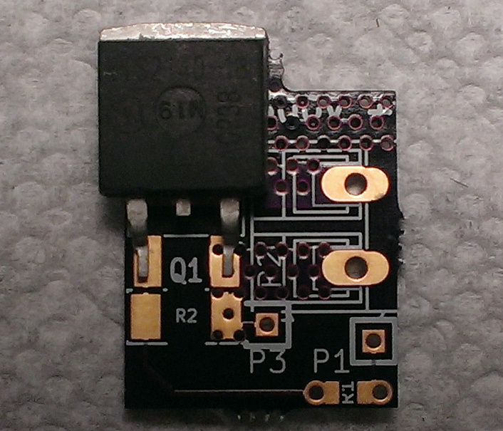
It works!kb1gtt wrote:See attached schematic captured in Dave CAD

red wire is 12V
white wire goes to low-side driver on Frankenso
green wire is alternator field
there is a diode under the tape
blue wire is GND
with 35% duty @ 400Hz, I've got ~0.8 volts of charging (12.2 becomes 13v)
diode<>GND: 0.8A
field wire<>field wire: ~1.2A
I then proceed to a higher duty cycle - probably 80% (?), got 6A in the field wire<>field wire, a lot of charge, and melting solder with nasty smell in 10 seconds. Mental note: do not try this with duty above 50%.
PS: we need to add diode support into the DDPAK board. Could it be a surface-mount diode, or does it have to be a through-hole?
Very limited telepathic abilities - please post logs & tunes where appropriate - http://rusefi.com/s/questions
Always looking for C/C++/Java/PHP developers! Please help us see https://rusefi.com/s/howtocontribute
Always looking for C/C++/Java/PHP developers! Please help us see https://rusefi.com/s/howtocontribute
Re: Alternator voltage control
Thanks for the data points. I'll have to re-spin the DPAK board to add some components.
Also good read found here, and attached in PDF form to prevent bit-rot.
http://www.embedded.com/design/real-time-and-performance/4006472/Designing-a-microcontroller-driven-alternator-voltage-regulator
Also good read found here, and attached in PDF form to prevent bit-rot.
http://www.embedded.com/design/real-time-and-performance/4006472/Designing-a-microcontroller-driven-alternator-voltage-regulator
- Attachments
-
- www.embedded.pdf
- (739.04 KiB) Downloaded 370 times
Welcome to the friendlier side of internet crazy
Re: Alternator voltage control
I see chips like this L9409F exist which includes pretty much all the parts, diode, MOSFET, ect in one chip. Makes for easy work and less parts to keep track of, as well it comes with thermal overload. http://octopart.com/l9409f-stmicroelectronics-18031937
Can we find a readily available chip like this to be used as the alt regulator?
Can we find a readily available chip like this to be used as the alt regulator?
Welcome to the friendlier side of internet crazy
-
AndreyB
- Site Admin
- Posts: 14332
- Joined: Wed Aug 28, 2013 1:28 am
- Location: Jersey City
- Github Username: rusefillc
- Slack: Andrey B
Re: Alternator voltage control
google "Alternator Regulator chip" returns a lot of options, none of which are available for sale in low quantities.
Very limited telepathic abilities - please post logs & tunes where appropriate - http://rusefi.com/s/questions
Always looking for C/C++/Java/PHP developers! Please help us see https://rusefi.com/s/howtocontribute
Always looking for C/C++/Java/PHP developers! Please help us see https://rusefi.com/s/howtocontribute
Re: Alternator voltage control
junk yard is your friend
Re: Alternator voltage control
I found this one http://octopart.com/l9484-stmicroelectronics-13884940 but price is a bit of a yuck.
Welcome to the friendlier side of internet crazy
Re: Alternator voltage control
Turns out that if you click that octopart link for newark, they don't have it. So that was blah. Here are some that seem to be actually available.
http://octopart.com/l9911p-stmicroelectronics-18034601 $8.93
http://octopart.com/l9911f-stmicroelectronics-18034875 $8.75
http://octopart.com/l9914b-stmicroelectronics-18034602 $10.50
http://octopart.com/l9914c-stmicroelectronics-20571333 $10.71
http://octopart.com/l9911p-stmicroelectronics-18034601 $8.93
http://octopart.com/l9911f-stmicroelectronics-18034875 $8.75
http://octopart.com/l9914b-stmicroelectronics-18034602 $10.50
http://octopart.com/l9914c-stmicroelectronics-20571333 $10.71
Welcome to the friendlier side of internet crazy
-
AndreyB
- Site Admin
- Posts: 14332
- Joined: Wed Aug 28, 2013 1:28 am
- Location: Jersey City
- Github Username: rusefillc
- Slack: Andrey B
Re: Alternator voltage control
So which one should I order if I should order any? They are definitely not cheapkb1gtt wrote:Here are some that seem to be actually available.
http://octopart.com/l9911p-stmicroelectronics-18034601 $8.93
http://octopart.com/l9911f-stmicroelectronics-18034875 $8.75
http://octopart.com/l9914b-stmicroelectronics-18034602 $10.50
http://octopart.com/l9914c-stmicroelectronics-20571333 $10.71
Do we need some heatsinking huge-via areas around the proto areas on Frankenso?
Very limited telepathic abilities - please post logs & tunes where appropriate - http://rusefi.com/s/questions
Always looking for C/C++/Java/PHP developers! Please help us see https://rusefi.com/s/howtocontribute
Always looking for C/C++/Java/PHP developers! Please help us see https://rusefi.com/s/howtocontribute
Re: Alternator voltage control
I would say go with the L9911F, it's the lower cost and it has a better datasheet. It looks like you'll have to PWM the P signal, as that will cause problems if the charging circuit if it does not have a proper signal. In your case the Neon doesn't have the P field wire so you can't get that from the alt. I'm not sure what it does if you are in a fault detected state. See page 16 of this datasheet http://datasheet.octopart.com/L9911F-STMicroelectronics-datasheet-10836994.pdf I don't know if it just triggers that DFM line or if it does something else.
If we can find a thermally protected P-MOSFET, I'd like that. I could mount the diode near the MOSFET such that if the diode gets to hot it triggers the MOSFET protection. However so far no dice in finding a good P-MOSFET with a 10 to 20A capability.
If we can find a thermally protected P-MOSFET, I'd like that. I could mount the diode near the MOSFET such that if the diode gets to hot it triggers the MOSFET protection. However so far no dice in finding a good P-MOSFET with a 10 to 20A capability.
Welcome to the friendlier side of internet crazy
-
AndreyB
- Site Admin
- Posts: 14332
- Joined: Wed Aug 28, 2013 1:28 am
- Location: Jersey City
- Github Username: rusefillc
- Slack: Andrey B
Re: Alternator voltage control
OMG this link is amazing, is not that exactly what I need for my alternator control?Snokpelle wrote:You should not choose a discrete MOSFET as a driver for a signal or source going out from an ECU...kb1gtt wrote:Why is it so hard to find protected MOSFET's?
I've been looking for a P-Channel, thermally protected, 10amp or more, enhanced mode MOSFET, DPAK or D2PAK, preferably with a voltage clamp protection.
Example of ST's HSS-devices (you should find devices up to 100Amp without problems):
http://www.st.com/web/en/catalog/sense_power/FM1965/SC1037
VN750PS-E is available in qty 1 from some suppliers I've never used - http://octopart.com/partsearch#!?q=VN750PS-E
and VN5160S-E is available from everywhere including digikey http://octopart.com/partsearch#!?q=VN5160S-EVN750 Series Single 6 A 36 V 60 mOhm Surface Mount High-Side Driver - SOIC-8
if these use the same pinout on SO-8 that would be really nice.
Very limited telepathic abilities - please post logs & tunes where appropriate - http://rusefi.com/s/questions
Always looking for C/C++/Java/PHP developers! Please help us see https://rusefi.com/s/howtocontribute
Always looking for C/C++/Java/PHP developers! Please help us see https://rusefi.com/s/howtocontribute
Re: Alternator voltage control
As noted above and here http://rusefi.com/forum/viewtopic.php?f=4&t=286&start=55 This is the list I think we should consider for a thermally protected P-MOSFET, apparently called a Hight Side Switch (HSS) by ST.
For above 1A I get concerned with using SO-8 packages as the heat will be hard to get out of the chip and it will be hard to uphold the rated amp of that chip. Much like the hi/low is only able to do 1/8 amps when it's technically rated for 2A. The thermal properties become important when you go higher in current.
$4.20 2ch http://octopart.com/vnd5e025aktr-e-stmicroelectronics-17417297 also has eval board http://octopart.com/ev-vnd5e025ak-stmicroelectronics-25737927 for $20
$3.25 2ch http://octopart.com/vnd7020ajtr-e-stmicroelectronics-30039249
$3.18 2ch http://octopart.com/vnd5e025mktr-e-stmicroelectronics-18186948
$3.95 2ch http://octopart.com/vnd5e025bktr-e-stmicroelectronics-21218838
$2.38 1ch http://octopart.com/vn7020ajtr-e-stmicroelectronics-31115209
$2.99 1ch http://octopart.com/vnd7030ajtr-e-stmicroelectronics-30039251
My favorite is VND5E025AK-E, as it has 3 potential drop in replacements so it should be good for long term and it has an off the shelf eval board so faster development cycle. Then my next runner up is VND7020AJ-E because it's cheapest per channel.
Code: Select all
$/1	  PT#	        ch  volts amps mohm Vmax '$/ch	pkg           notes
$3.25	VND7020AJ-E	 2	28	63	22	40	$1.63	PowerSSO-16
$2.38	VN7020AJ-E	  1	28	63	20	40	$2.38	PowerSSO-16
$2.99	VND703AJTR-E	1	28	56	31	40	$2.99	PowerSSO-16
$3.95	VND5E025BK-E	2	28	60	25	41	$1.98	PowerSSO-24
$4.20	VND5E025AK-E	2	28	60	25	41	$2.10	PowerSSO-24	Eval $20
$4.20	VND5E025MK-E	2	28	60	25	41	$2.10	PowerSSO-24
Welcome to the friendlier side of internet crazy
-
AndreyB
- Site Admin
- Posts: 14332
- Joined: Wed Aug 28, 2013 1:28 am
- Location: Jersey City
- Github Username: rusefillc
- Slack: Andrey B
Re: Alternator voltage control
You are the boss. Need a boardkb1gtt wrote:My favorite is VND5E025AK-E, as it has 3 potential drop in replacements so it should be good for long term
2nd channel would be useful if someone needs VTEC with constant 2A current.
Very limited telepathic abilities - please post logs & tunes where appropriate - http://rusefi.com/s/questions
Always looking for C/C++/Java/PHP developers! Please help us see https://rusefi.com/s/howtocontribute
Always looking for C/C++/Java/PHP developers! Please help us see https://rusefi.com/s/howtocontribute
-
AndreyB
- Site Admin
- Posts: 14332
- Joined: Wed Aug 28, 2013 1:28 am
- Location: Jersey City
- Github Username: rusefillc
- Slack: Andrey B
Re: Alternator voltage control
russian wrote:You are the boss. Need a board
 just placed an order
Very limited telepathic abilities - please post logs & tunes where appropriate - http://rusefi.com/s/questions
Always looking for C/C++/Java/PHP developers! Please help us see https://rusefi.com/s/howtocontribute
Always looking for C/C++/Java/PHP developers! Please help us see https://rusefi.com/s/howtocontribute
-
AndreyB
- Site Admin
- Posts: 14332
- Joined: Wed Aug 28, 2013 1:28 am
- Location: Jersey City
- Github Username: rusefillc
- Slack: Andrey B
Re: Alternator voltage control
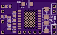
PowerSSO-24 board has arrived. Need pin#1 marker and the larger heatsink vias would be easier to work with, but the main thing is that everything aligns right.
I do not have the diodes yet, how essensial are they to try the board?
I do not have the diodes yet, how essensial are they to try the board?
- Attachments
-
- PowerSSO-24.jpg (128.23 KiB) Viewed 22049 times
Very limited telepathic abilities - please post logs & tunes where appropriate - http://rusefi.com/s/questions
Always looking for C/C++/Java/PHP developers! Please help us see https://rusefi.com/s/howtocontribute
Always looking for C/C++/Java/PHP developers! Please help us see https://rusefi.com/s/howtocontribute
Re: Alternator voltage control
The diode is critical, needed for fly-back topology.
Added reminder in knownissues.txt about the pin1 indicator.
Added reminder in knownissues.txt about the pin1 indicator.
Welcome to the friendlier side of internet crazy
-
AndreyB
- Site Admin
- Posts: 14332
- Joined: Wed Aug 28, 2013 1:28 am
- Location: Jersey City
- Github Username: rusefillc
- Slack: Andrey B
Re: Alternator voltage control
Looks like the hardware side of Dodge Neon high-side field control wire is taken care of now, next step the software.
Check the video - notice how voltage changes bit by bit while I am increasing PWM duty cycle, and then it suddenly runs away. Looks like PID would be needed?
[video][/video]
Check the video - notice how voltage changes bit by bit while I am increasing PWM duty cycle, and then it suddenly runs away. Looks like PID would be needed?
[video][/video]
Very limited telepathic abilities - please post logs & tunes where appropriate - http://rusefi.com/s/questions
Always looking for C/C++/Java/PHP developers! Please help us see https://rusefi.com/s/howtocontribute
Always looking for C/C++/Java/PHP developers! Please help us see https://rusefi.com/s/howtocontribute
Re: Alternator voltage control
Very nice, very nice. In terms of software you probably want to filter the analog signals some, to smooth out that needle. The PID will not like the noise either.
How hot did the chip get?
How hot did the chip get?
Welcome to the friendlier side of internet crazy
-
AndreyB
- Site Admin
- Posts: 14332
- Joined: Wed Aug 28, 2013 1:28 am
- Location: Jersey City
- Github Username: rusefillc
- Slack: Andrey B
Re: Alternator voltage control
I think it was slightly warmer then the rest of the engine bay in that area.kb1gtt wrote:How hot did the chip get?
Very limited telepathic abilities - please post logs & tunes where appropriate - http://rusefi.com/s/questions
Always looking for C/C++/Java/PHP developers! Please help us see https://rusefi.com/s/howtocontribute
Always looking for C/C++/Java/PHP developers! Please help us see https://rusefi.com/s/howtocontribute
-
AndreyB
- Site Admin
- Posts: 14332
- Joined: Wed Aug 28, 2013 1:28 am
- Location: Jersey City
- Github Username: rusefillc
- Slack: Andrey B
Re: Alternator voltage control
Now configurable via Tuner Studio

Very limited telepathic abilities - please post logs & tunes where appropriate - http://rusefi.com/s/questions
Always looking for C/C++/Java/PHP developers! Please help us see https://rusefi.com/s/howtocontribute
Always looking for C/C++/Java/PHP developers! Please help us see https://rusefi.com/s/howtocontribute
Re: Alternator voltage control
Great and thanks for that offset thing. One request, can you put a note on it some where that notes output % duty = Pterm + Iterm + Dterm + offset%
Hmmmm, it might also be good to also post the general algo some where on that screen. Such that those of us who want to know the details of what kind of PID we are dealing with (mostly how the I term is handled) it would help show that with out requiring jumping into the code.
As a note to others who might come across this thread. The offset is for a kind of manual tuning. For example, if the P, I and D set to 0, the output will equal the offset% which means manual control. You can then manually adjust the output duty until you reach 14V. At this point you know what the PID loop should be adjusting too, which can be handy when tuning. AKA if you know where you should be you'll have some insight to see if you are getting there correctly.
Welcome to the friendlier side of internet crazy
-
gptech2444
- Posts: 46
- Joined: Mon Jan 22, 2018 9:01 pm
Re: Alternator field control circuit
What was the end result of the alternator control?
I ended up getting a westfield alternator board for my 2003 MX5.
I ended up getting a westfield alternator board for my 2003 MX5.