We have that sweet prototyping area and some people do not have OEM MAP sensor. I guess we need a tiny PCB with the footprint of MPXH6400 - that's a tiny MAP sensor.
Looks like it's small enough that we can have it on it's side inside the case - this case the hose can go through a side wall.
If one has two of these, the second one could be used for baro pressure.
abecedarian wrote:Have a particular 'pad layout' you'd like?
If the question is about the device package, then something small so that we can have a tiny board and have an option to mount the mini board at 90 degrees so that the nipple is parallel to the main board?
abecedarian wrote:Well
-6400 is good from 40-400 kPa, or round-about that...
-6115 is good from 10-115 kPa, give or take.
Looks like N/A applications would prefer 6115?
From PCB standpoint, does it matter? In case if the device footprint is the same we can call it 6115 and imply that 6400 could be used in place and vice verse.
Probably so. They cost about the same from distributors.
IIRC, 6115 does have samples available though.
You can lead the horticulture but you can't make them think.
A lot of DNP resistors to maybe provoke some sense of resistor / op-amp divider / buffering options, since it is an 'off board' intended thing, and who knows what's on-board?
Jared?
Last edited by abecedarian on Wed Dec 24, 2014 4:29 am, edited 1 time in total.
You can lead the horticulture but you can't make them think.
I believe I recognize that as Eagle, which is a free download.
I agree that the op-amp is a good idea. The op-amp adds pennies to the cost but allows proper signal conditioning over longer runs and significantly better quality of the captured signal. Some people will want to put this closer to the manifold to minimize mechanical warpage, while others will want to run shorter wires to avoid electrical noise. Perhaps allow an option for short electrical runs to have 0R's installed.
Can you make the op-amp happen to work with a 200 ohm resistor installed at the MCU? AKA, at 5V op-amp can drive 20mA, that would be handy, as it would allow a low impedance signal line for longer runs, which would decrease influence of electrical noise. I choose 5V and 200 ohms as that's a common setup for 4-20 current loops.
About connector, is there a 5V friendly series of boards out there that we should model the connector after? Arduino shields are kind of large, I just noticed that UEXT are 3.3V, but I have 5V at the Frankenso. Perhaps papilio wings would be good. Hmmm, that seems to also provide not only 3.3V but also 2.5V.
I think I like the papilio 8bit wing the best. I'm going to space the 5V and GND such that a wing could potential work. If I can reasonably get 3V over there I'll try to get it there as well. If we should consider some other connector please speak up. For now I'm going to add the 5V and GND to the proto area on Frankenso like the 8 bit wing unless someone convinces me of something different.
I'd like to make the break out work friendly with some series of off the shelf boards.
kb1gtt wrote:About connector, is there a 5V friendly series of boards out there that we should model the connector after? Arduino shields are kind of large
I think any connector would be a huge waste of space, it's not like we have a huge prototype area. I'd say simply 0.1" spacing through-holes and wires would do the job.
If we want to make a bit nicer we can connect the through holes in pairs with a trace - this case one hole is used to solder module pin and the neighboring hole is used to solder a wire. Until we have enough installations it's simply impossible to guess what's the best way to do it.
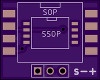
The board I'm thinking of doing would be a 2-layer, 5cm^2 module, maybe smaller once I start on and optimize layout. The thought here is many board fabs have price breaks and such, and that is a common size for many 'generic' modules, easy to panelize and such, and I am planning on having 3mm holes at each corner to facilitate secure mounting. My use would have this mounted on top of another board, secured at each corner, and with short pin headers between this and the parent board, not with off-board connectors. If I were going to do some sort of connector system, the board itself would probably only provide for wires to be soldered in, which would lead out to a female/male, 5 position, sealed connector, 14 AWG/1.63mm diameter wire, pigtail / harness pair similar to what many sensors would otherwise use in an automotive situation. Why 5 wires you ask? 5vdc in, baro-out, MAP-out, ground to ECU, local ground to chassis.
Another consideration for this would be that the two sensors are actually meant to be part of a sealed module and as such do not have barbed hose fittings so any hose attached may be prone to falling off. Solutions for this could be either chemical bonding or spin-welding a proper hose fitting to them, or having a bulk-head fitting directly over the inlet that holds a small section of hose/pipe securely to the sensor and also which exposes a barbed port externally; in particular the 6400, if it's used with a forced-induction engine, would require something for a better, mechanical connection.
Similarly, if not being used for forced induction, a 6115 could be used for MAP. One benefit of this is there are 3v3 versions of the 6115 available, and as such would be a better fit for many microcontrollers, making any op-amp configuration only require be to install resistors which configure it for unity-gain / buffer.
You can lead the horticulture but you can't make them think.
About a connector, I'm not trying to force a connector, I'm trying to make it semi friendly to buy off the shelf hardware and make it easier for developers to get involved. Less soldering is a bonus for many soft dev's. I'm trying to figure out where I should put the 5V and GND pads and such on the proto board area. I figure if I put them where an off the shelf module might be able to be soldered in, it makes it easier for the soldering side of things. So no worries if the module design uses jumper wires. I just wanted to mention it such that if the module is selecting where the 5V and GND should be, it might be an easy plug in device.
I need to order these sensors, does anyone have one to validate the footprint?
I think we do not need a mounting hole - the solder pins would hold this in place, this thing is pretty light. We also need to make the board three times smaller - simply because that's going to be inside the same and there is not much space. Please move the pins to the edge of the board so that the board could be installed vertically with 90 degrees angle pins.
Tomin wrote:Is 40kPa usable minimum pressure? I thought there could be even lower pressure on idle.
Tomin
Keep in mind these sensors are "absolute": 0 kPa would be an absolute vacuum and ~101.3kPa would be the mean atmospheric pressure at sea level. Similarly, ~202.6kPa would equal approximately 14.7PSI boost, et cetera.
40kPa [absolute] is actually a quite strong vacuum you might encounter such as when closing the throttle at relatively high RPM.
For comparison, at 100km elevation, the common definition of where "space" begins, air pressure is about 3.2kPa; at 30,000 feet is about 30kPa; Mt. Everest is about 34kPa.
You can lead the horticulture but you can't make them think.
Hello guys , im trying to get the capasitors and resistors for this module , can somene tell me what kind components should i buy ? I checked digikey and mouser they have them but there is alot of different components. I need the exact components used for this map board excluding the actual MPXH6400 sensor. Thanks.