Hi, i have question about wire up distributor to microRusEfi.
It is possible?
I also need find out some tooth pattern for G13B distributor. I try check out actual supported patterns, but a cannot find any similar.
Thanks for any help to do it run!
Re: Distributor wiring and tooth pattern
Posted: Sun Oct 03, 2021 8:27 pm
by AndreyB
Please provide more details. I am not familiar with G13B distributor please mention vehicle and year. As is I am not sure what are you trying to do.
Re: Distributor wiring and tooth pattern
Posted: Sun Oct 03, 2021 8:38 pm
by mihallis
First in first sorry for my English.
I'm trying to setup microRusEFI for Suzuki Swift G13B engine (G13B 74 kW), that engine does not have any VR or Hall sensor, only distributor, with toothed wheel. So probably, it is possible to use that distributor instead of VR/Hall sensor.
So in this case i have now. I need setup right tooth count. But that distributor have 1 double tooth so output signal will be something like this...
_|_|____|____|____|
In this moment. I'm very confused. Sorry for that.
If something does not make sense, please ask me about that other way.
Re: Distributor wiring and tooth pattern
Posted: Sun Oct 03, 2021 8:42 pm
by AndreyB
Distributor with one double tooth is not just a plain old distributor.
Is there a chance that inside that distributor there is some sensor?
Please note
has three VR sensors inside the not so plain distributor ASSEMBLY.
Mazda miata has two Hall sensors inside the distributor ASSEMBLY.
Please post wiring diagram of that distributor. If you have output signals into some electronics that's a hybrid unit.
Re: Distributor wiring and tooth pattern
Posted: Sun Oct 03, 2021 9:20 pm
by mihallis
The distributor has only one sensor. But wheel inside have one "double" tooth and other three teeth. I cannot find any photos, i'll take one tomorrow.
That one sensor probably will be Hall and probably output will be (by looking to teeth).
_|_|____|____|____|___.
Sorry, it's G13BB not G13B.
Re: Distributor wiring and tooth pattern
Posted: Sun Oct 03, 2021 9:40 pm
by AndreyB
I am starting to think that you are asking how to get this custom shape working in rusEFI
In order to get a new shape working in rusEFI C/C++ code would have to be changed to add new shape definition. For me to add new shape definition I need exact angle positions of the tooth or at least a straight symmetrical picture of the wheel.
For me to add new shape definition I need exact angle positions of the tooth or at least a straight symmetrical picture of the wheel.
I suspect it's one tooth per cylinder, plus an extra tooth in the center between two cylinders. An N+1 wheel, if you will.
Re: Distributor wiring and tooth pattern
Posted: Mon Oct 04, 2021 6:19 am
by MHTSOS
As far as I know the G13BB has wasted spark ignition with two coils on the valve cover. The G13B had a distributor. Is this engine from a Suzuki Swift GTi or another car? Is it the 100hp version? Does it have 1 cam or dual cams?
Στάλθηκε από το VOG-L29 μου χρησιμοποιώντας Tapatalk
It's G13B from Suzuki Baleno - mainly, but in some cases it could be find in Swift as 63kW version. It's EFI engine with this distributor.
G13B and G13BB is similar. but have many variations. So it's all confusing.
G13B is with "classic" distributor (SOHC or DOHC GTi) + EFI.
G13BB is SOHC only with wasted spark + EFI.
I have SOHC + EFI + no wasted spark (w distributor)
How to setup this pattern?
Re: Distributor wiring and tooth pattern
Posted: Mon Oct 04, 2021 9:52 am
by MHTSOS
This is a 4+1 like Mathew predicted. It will probably need a custom trigger built into the software. It it possible to install a cranck wheel like 36-1 with a generic sensor and not use the signal from the distributor at all? That would be the most reliable solution. A cam wheel with only 4 teeth does not provide a lot of resolution.
Στάλθηκε από το VOG-L29 μου χρησιμοποιώντας Tapatalk
Re: Distributor wiring and tooth pattern
Posted: Mon Oct 04, 2021 10:59 am
by mihallis
Yes it is possible.
But only like this (Suzuki OE 12630-52G01):
image.png
Re: Distributor wiring and tooth pattern
Posted: Mon Oct 04, 2021 11:57 am
by MHTSOS
That's 36-2-2-2 and it's already supported. It's the same as Subaru. This will work fine.
Στάλθηκε από το VOG-L29 μου χρησιμοποιώντας Tapatalk
Re: Suzuki G13B tooth pattern
Posted: Mon Oct 04, 2021 10:50 pm
by AndreyB
Let me attempt to add new trigger
Re: Suzuki G13B tooth pattern
Posted: Mon Oct 04, 2021 11:51 pm
by AndreyB
Next step is testing on real car, be sure to use a timing gun to figure out "global trigger offset"
Re: Suzuki G13B tooth pattern
Posted: Tue Oct 05, 2021 7:21 am
by JRD McLAREN
It is trigger pattern in distributor,
it count 720deg, not 360 only.
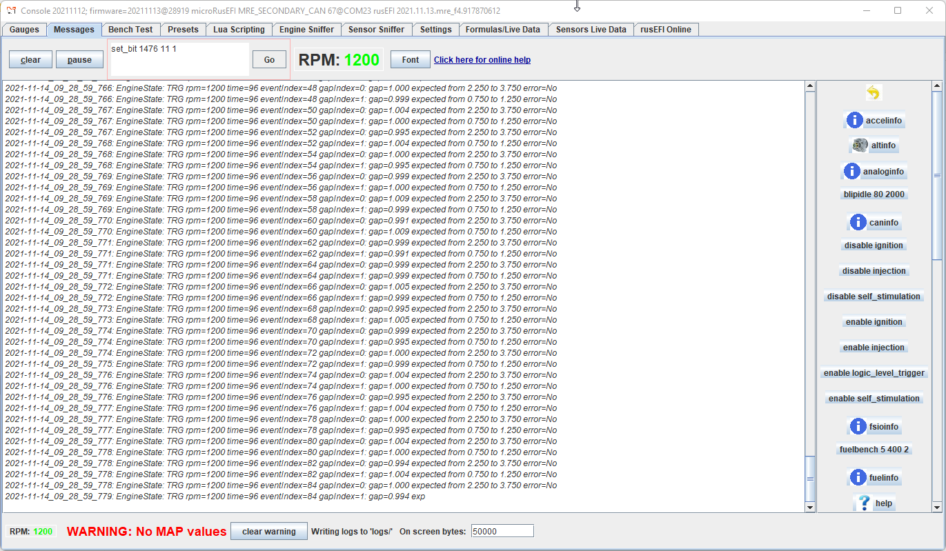
Next step is testing on real car, be sure to use a timing gun to figure out "global trigger offset"
Hi, Thank you!
We tried it today and we got message WARNING: Shaft event while trigger is mis-configured. But nothing seems as bad configuration, it is bad wiring ? or where we should start with debugging problem.
Oh! Thanks... we forgot about it, we thinked if it is disabled, then is not take to the mind. So we were ignored that.
Tomorrow we could say, if it's working and if it is right.
We have this setup:
image.png
Re: Suzuki G13B tooth pattern
Posted: Sun Nov 14, 2021 7:59 pm
by AndreyB
At the moment you have ignored the "please provide data" part. Is there a misunderstanding that just changing CAM setting would improve things? It would not.
Without the verbose data I have asked for to the best of my ability this would not just solve itself.
Re: Suzuki G13B tooth pattern
Posted: Sun Nov 14, 2021 8:40 pm
by mihallis
Sorry, we try it tomorrow and get more info if problem persist and more logs from console. At this moment we're not at the car.
Re: Suzuki G13B tooth pattern
Posted: Sat May 03, 2025 11:27 pm
by JoaoSantos0
Hi! I saw that you successfully installed a Rusefi ECU on a Suzuki G13B engine (Baleno 1.3 16v 1998/99), which is exactly the same project I’m working on.
I’m reaching out to ask if you could share some details of your setup:
• Full ECU pinout (how you connected sensors, injectors, ignition, relays, etc.)
• Are you using the original CKP sensor with the 36-2-2-2 trigger wheel like I am?
• Are you running sequential or semi-sequential injection/ignition using only the crank sensor?
• What base map did you use? Would you be willing to share your TunerStudio .msq file?
I’ve been advised to use:
• Ignition coil from an Opel Corsa 1.4 16v (4 wires, wasted spark)
I’m trying to use as many original sensors as possible and would like your input. I’m considering keeping sensors like:
• IAT
• CLT
• TPS
• CKP
Any help or guidance would be greatly appreciated. Thank you!