I've yet to see any official documentation on shielding for the wires (I'll check my service manual), but some searching turned up a picture where it looks like all 3 pairs of vr wires are bundled into the same shield. And as a reminder, I'm using all stock wiring with the addition of a jumper harness to change the ecu connectors, so the shield should still be connected to wherever it needs without my intervention.
Anyway, for more exciting news, it seems to be working (not the engine, the trigger). I removed the W1001 and W1002 jumpers, and got to work scoping the sensors. I'll attach the scope traces but they didn't end up being that important (good background info though). Scope traces at the distributor and the ecu ends both showed textbook vr outputs with peak-to-peak voltages of about 15v and fairly clear edges, so I went on to reconnect the frankesno and get cranking again. I found I would get an rpm spike on starting cranking, which would then drop to 0rpm. The solid trigger LEDs seem to have gone away with the jumpers, so I was basically out of ideas. Eventually, while agonizing over the trigger settings in TunerStudio, I realized my real mistake. Can you see it?

- BAD SETTINGS! TOOTH COUNT SHOULD BE 8 (even though it's really 16)
- 2017-02-06-224809_396x699_scrot.png (32.4 KiB) Viewed 16543 times
It occurred to me that my "crank" trigger is a wheel in my distributor, and my distributor is turned by my camshaft which, long story short, spins at half the rate of my crank. Rather than having 16 teeth, my crank trigger effectively has 8. Upon fixing this setting, and undoing all my other misguided efforts, I found I have a proper cranking signal and decent captures from the sniffer.
I got a bit overzealous and decided to try and start the motor (simultaneous fuel, only 3/4 injectors working :p), but got a backfire out of the motor and decided I had better wait until I have a properly constructed base tune before trying that again. Hopefully I'll have the motor idling on rusefi by the end of the week. Below find attached a bunch of scope traces and captures for future reference. 2v/5ms per division, 1x probe for all traces. Noise on channel A may be due to a loose terminal (why some are on B)
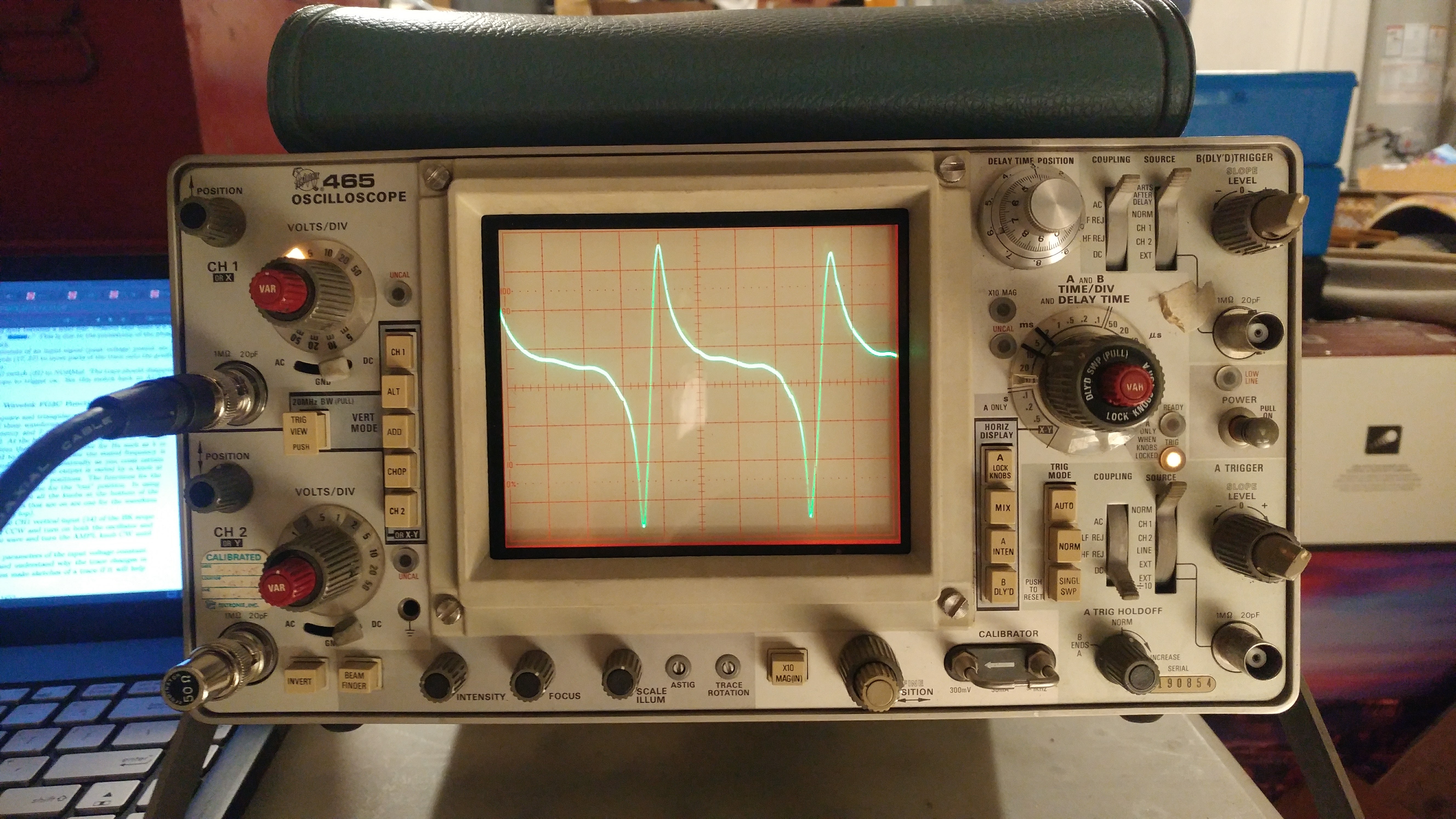
- Cam position sensor, idling - captured at distributor
- 20170206_203652.jpg (3.33 MiB) Viewed 16543 times

- Cam position sensor, idling - captured at ecu
- 20170206_210032.jpg (2.94 MiB) Viewed 16543 times

- Crank position sensor, idling - captured at distributor
- 20170206_211345.jpg (3.26 MiB) Viewed 16543 times

- Crank position sensor, idling - captured at ecu
- 20170206_205713.jpg (3.22 MiB) Viewed 16543 times

- Crank position sensor, cranking - captured at distributor
- 20170206_212046.jpg (3.08 MiB) Viewed 16543 times

- Sniffer of brief cranking with plugs installed. Secondary trigger is 4 tooth wheel, not cam position sensor.
- 2017-02-06_21_50_43rpm_0_maf_NaN.png (19.72 KiB) Viewed 16541 times


