

Hi everybody,
I am new to this forum but have been interested in rusEFI for a couple of years. Until now i didn't have a specific reason to use it. That changed just this week, as i blew up the engine in my engine swapped Volvo 850 from 1997. The engine came out of a 1996 Volvo 850 T5. On one of the first test drives, due to lean burn conditions, while trying a unknown Bosch Motronic 4.4 ECM from a later Volvo V70 model one of the cylinders overheated and the piston failed. This week i have been debating what to do about that and aquired a new to me B5204T4 engine out of a V70 Volvo from about 2006. The issue with that is, that the engine is slightly different to the previous one, but the block is prety similar. One option would have been to change the head, but i am unsure if the head of the blown motor is ok. And i like the idea of individual ignition coils instead of the distributer on the new engine. But the wiring loom obviously doesn't work for that now.
So i have come to the conclusion that i want to install the RusEFI. Now comes the issue of money. As i am a student right now i am on a tight budget, so i would like to the uaEFI directly from JLCPCB and distribute the other 4 ECUs to other people.
My final goal is a PnP ECU that replaces the stock Fenix/Motronic ECU in the late 90s models of volvo 5 cylinder engines, but i still have to learn quite a bit until then about pcb design. Plan is also to make that design open source once done.
A few questions i have:
1. The engine has two Knock sensors, one on cylinder 2 and one on cylinder 4, but uaEFI only has one input. Could i modify the board layout to use one of the auxilary analog input for the other one, adding the knock circuit to it?
2. When looking into question 1. i noticed that the VR Input is connected to the same Analog3 pin as the Knock sensor through resistors. What is this about?
3. Befor designing a PCB i think it would be a better option to try making the uaEFI work to get familiar with the whole rusEFI ecosystem. What is your take on that?
Looking forward to hearing your opinion,
Sebastian
1997 Volvo 850 with B5204T engine
-
DrahtFahrzeugHammer

- Posts: 18
- Joined: Wed Jul 23, 2025 9:07 am
- Location: Bavaria, Germany
- Github Username: DrahtFahrzeugHammer

-
mpgmike

- Posts: 95
- Joined: Thu Aug 15, 2024 2:49 pm
- Location: Oklahoma, USA
Re: 1997 Volvo 850 with B5204T engine
Knock input is a dedicated input on D14, while your VR inputs are C16 through C19. Not sure about the rest of your questions, but at least there is one dedicated knock input, and it's not in conflict with VR inputs.
'95 Jeep Grand Cherokee, 4.6 Stroker
-
DrahtFahrzeugHammer
- Posts: 18
- Joined: Wed Jul 23, 2025 9:07 am
- Location: Bavaria, Germany
- Github Username: DrahtFahrzeugHammer
Re: 1997 Volvo 850 with B5204T engine
So if i understand the circuit in the image correctly R5 is not placed, but R6 is 0 Ohms. Meaning you can disable Knock to utilize VR_Discrete?
The image is from the uaEFI Schematic
You do not have the required permissions to view the files attached to this post.
-
AndreyB

- Site Admin
- Posts: 14765
- Joined: Wed Aug 28, 2013 1:28 am
- Location: Jersey City
- Github Username: rusefillc
- Slack: Andrey B
Re: 1997 Volvo 850 with B5204T engine
No.
Very limited telepathic abilities - please post logs & tunes where appropriate - http://rusefi.com/s/questions
Always looking for C/C++/Java/PHP developers! Please help us see https://rusefi.com/s/howtocontribute
Always looking for C/C++/Java/PHP developers! Please help us see https://rusefi.com/s/howtocontribute
-
DrahtFahrzeugHammer
- Posts: 18
- Joined: Wed Jul 23, 2025 9:07 am
- Location: Bavaria, Germany
- Github Username: DrahtFahrzeugHammer
Re: 1997 Volvo 850 with B5204T engine
What is that supposed to do then?
-
DrahtFahrzeugHammer
- Posts: 18
- Joined: Wed Jul 23, 2025 9:07 am
- Location: Bavaria, Germany
- Github Username: DrahtFahrzeugHammer
Re: 1997 Volvo 850 with B5204T engine
Some progress has been made:
I ordered and received 5 Proteus and Volvo adapter boards for the Volvo ECU connector and am currently in the process of figuring out the wiring.
Does someone know if you can still get only the connector for those ECUs? The female connector is separated into two pieces with the same pin count of 43 pins. As far as i know this connector has been used on all 90s Volvo 850s and V70s with different ECUs, for example the Bosch Motronic 4.3 and 4.4 as well as some Siemens ECU. It was probably also used on some other models.
Here are Pictures of the ECU with connector In this case it was a Bosch Motronic 4.3:
I will keep this page updated with the progress i make
You do not have the required permissions to view the files attached to this post.
-
DrahtFahrzeugHammer
- Posts: 18
- Joined: Wed Jul 23, 2025 9:07 am
- Location: Bavaria, Germany
- Github Username: DrahtFahrzeugHammer
 Re: 1997 Volvo 850 with B5204T engine
The engine i am putting into the car has 4-wire coil on plugs from Bosch, Serial No.: 0 221 604 008. It can also be found as Volvo 9125601.
This is the wiring diagram i could find for that car: If i understand it correctly and from the research i have done pin 4 is for 12V power, 3 is for power ground, 1 is for driving the coil and 2 is for feedback?
As i am running a proteus board is there any way or reason to connect pin 2 for the feedback? Do i connect it to sensor-ground or just leave it floating?
Cheers
Sebastian
You do not have the required permissions to view the files attached to this post.
-
mpgmike
- Posts: 95
- Joined: Thu Aug 15, 2024 2:49 pm
- Location: Oklahoma, USA
Re: 1997 Volvo 850 with B5204T engine
You probably have an early version of the Ionic Feedback coils. It was used to detect misfires. I wasn't aware that they (pin #2) were all ganged together into a single ECU input. When a plug fires AND IGNITES THE A/F CHARGE, the pathway between the spark plug electrodes becomes somewhat conductive. The ECU measures the conductivity to determine if the plug actually fired the charge. I believe Volvo's executable was that if there was a misfire, the ECU would fire the coil a second time to at least mitigate emissions.
'95 Jeep Grand Cherokee, 4.6 Stroker
-
DrahtFahrzeugHammer
- Posts: 18
- Joined: Wed Jul 23, 2025 9:07 am
- Location: Bavaria, Germany
- Github Username: DrahtFahrzeugHammer
Re: 1997 Volvo 850 with B5204T engine
Thank you for that information. I guess i just leave that pin disconnected.
Judging by your statement this is not supported by RusEFI yet? Would the proteus hardware be able to do that at all?
From how i understand it you would need to measure current between pin2 and ground? Or does one measure the voltage?
Judging by your statement this is not supported by RusEFI yet? Would the proteus hardware be able to do that at all?
From how i understand it you would need to measure current between pin2 and ground? Or does one measure the voltage?
-
kb1gtt

- contributor

- Posts: 3779
- Joined: Tue Sep 10, 2013 1:42 am
- Location: ME of USA
Re: 1997 Volvo 850 with B5204T engine
I don't think there is software to do anything with the feedback. I'm also not sure the potential of voltage spikes on that pin. I would guess this was originally connected to a ADC on an MCU. So perhaps ~10k ohm to GND. I'd wire like the schematic then to emulate the OEM ECU 10k to GND. If you think software might happen then perhaps consider putting that to an MCU pin. But for now I'd just wire it via 10k to GND and see if it seems to work.
Welcome to the friendlier side of internet crazy 
-
DrahtFahrzeugHammer
- Posts: 18
- Joined: Wed Jul 23, 2025 9:07 am
- Location: Bavaria, Germany
- Github Username: DrahtFahrzeugHammer
Re: 1997 Volvo 850 with B5204T engine
Turns out if i just went two pages further in the wiring diagram i would have had the answer to my question about connection:
The distinction between the two diagrams is NA engine for the first one i posted and Turbo for this one, so this one actually corresponds to the setup i have (more than the other at least)
I have already completed the wiring with the wires conecting together within the harnes and then going to the ecu, where i have it floating. If there is thoughts in the future about supporting that i can be a test bed (probably)
Tomorrow i will attempt to start the car after checking everything over electrically again.
You do not have the required permissions to view the files attached to this post.
-
DrahtFahrzeugHammer
- Posts: 18
- Joined: Wed Jul 23, 2025 9:07 am
- Location: Bavaria, Germany
- Github Username: DrahtFahrzeugHammer
Re: 1997 Volvo 850 with B5204T engine
Good News! I got the engine running. After a few hickups. Took me quite a while to find all the issues with the wiring and calibrating all the sensors. Then had issues with finding TDC due to the lack of a timing gun. Made it work with a SMD LED and a switch to the 5V trigger for Coil 1.
Tune and Log of the engine running can be found here:
https://rusefi.com/online/index.php?vehicleName=Wovlov&user_id=2658&sorts[uploadedMsq]=-1&sorts[uploadedLog]=-1
Video of first start will follow soon, as i will upload it to YouTube. (Yes it was the first start, even if it seems to run quite well)
A couple of issues /weirdness:
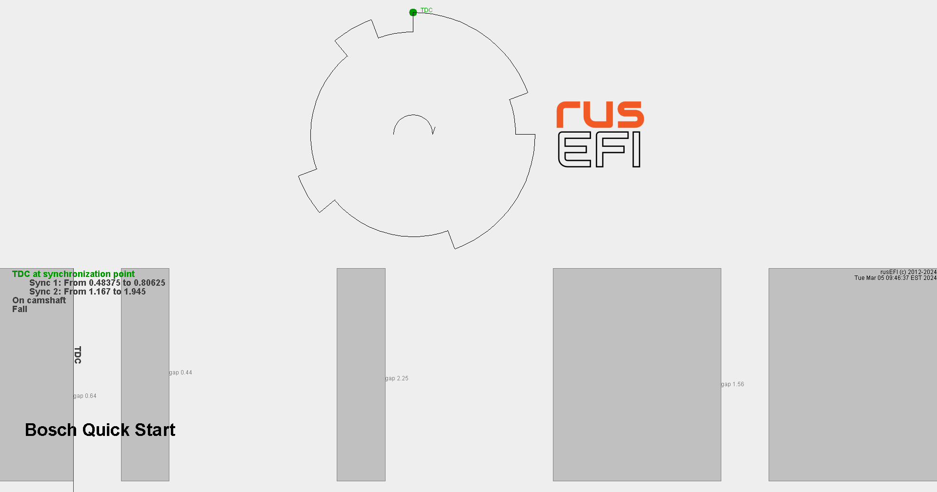
- the Bosch Quick start wheel seems to be spinning backwards compared to what it is supposed to look like here
this is what i get:
which probably explains, why it is doing wasted spark, even though that option is not turned on?
EDIT: i was looking through my images yesterday and found this picture of the trigger wheel on the exhaust cam: It looks just like the bosch quick start displayed on the supported triggers page, but it doesn`t spin clockwise, but counterclockwise: - It is running way too lean. Lamda tops out at 2 and sits around 1.6 idling even with the VE table cells there cranked up to 130(As can be seen in the logs). I guess i will have to find out what parameters i got wrong. The O2 sensor should be fine, i tested it with the exhaust of my motocycle and there it showed Lambda 0.9, just as it was adjusted with another O2 sensor a while ago. I am using mck1117's standalone module with carrier board btw.
I would very much appreciate some pointers to save me a bit of time
Edit: It is probably the MAP sensor being set up wrong. I calibrated it with atmospheric pressure at 96kPa and tested with the tire pressure gauge on shop air for 200kPa absolute (1 bar relative) and 300kPa (2 bar relative) and it seemed fine. But reviewing the logs, going down to 2 kPa seems a bit unlikely. I will do more tests with that later - Somehow i have to figure out how to get the tachometer and engine temp gauges to work on the dash. Any tips? The gauges seem to be controlled by a microcontroller. As a pointer the stock ECU was a Bosch Motronic 4.3
You do not have the required permissions to view the files attached to this post.
Last edited by DrahtFahrzeugHammer on Sun Sep 14, 2025 9:18 am, edited 2 times in total.
-
DrahtFahrzeugHammer
- Posts: 18
- Joined: Wed Jul 23, 2025 9:07 am
- Location: Bavaria, Germany
- Github Username: DrahtFahrzeugHammer
Re: 1997 Volvo 850 with B5204T engine
Update on the issue with high VE table numbers: I changed the calibration of the map sensor. It is not what the datasheet of the sensor suggests, neiter the settings i got through testing, but something in between. the MAP values are therefore not representative of the actual pressure in the manifold, but should be in the ballpark. As my setup is quite unique and cannot be found like that stock, and is very unlikely to be done like that (except maybe on the original car this engine is from, where the B5204T5 is originally mounted, somewhere between 2000 and 2007 in V70s or S80s) i will just make due with that and just tune with those wrong values. That means i have to redo the whole tuning if i decide to get the proper MAP values, but that is a bridge i am going to build later.
PS.: here is an image of the rats nest of a adapter board and the custom case i made to fit the stock ECU box. The picture is not from how it is right now, but prety close. Additionally the original ECU connector is not propperly pressed into the plug, so i will have to see if i will have some issues with losing connection due to vibrations. More images to come soon. I was mainly focusing on getting the car on the road. Now comes documentation and networking
Rats nest: Custom case: If there is interest, i will put it on printables or on github. I can also print them and send them, with the necessary hardware, the quality would not be the best at the moment, as my printer is not too well set up, because it is good enough for what i usually need
A picture i made while modifying the stupidly expensive exhaust (exhaust alone 2700€, ontop of that TÜV inspection, which included certification of the engine i put in the car another 1500€. That was not with RusEFI though. that is a problem for 2 year in the future me, when there is the next inspection)
I removed the catalytic converter on the advice of someone who was doing software development for production cars for many years, telling storries about catalytic converters that got too hot and disintegrated, taking the whole engine with them in the process.
You do not have the required permissions to view the files attached to this post.
-
DrahtFahrzeugHammer
- Posts: 18
- Joined: Wed Jul 23, 2025 9:07 am
- Location: Bavaria, Germany
- Github Username: DrahtFahrzeugHammer
Re: 1997 Volvo 850 with B5204T engine
Figured out why i had the wrong MAP values. It was due to me going off of the wrong datasheet. I thought i had the Bosch PST 4, but i actually have the Bosch PST 3. They differ in the pressures they can measure. PST 3 can do 0.2 to 3 bar absolute and PST 4 can do 0.4 to 4 bar.
Still in the process of figuring out the tachometer and CLT gauges. I measured on the stock ecu and looked up the chip the outputs connect to and it turns out they are lowside outputs, but i wired them up as 5v ignition outputs. I added the 100 Ohm resistors from the stock ecu inline, just as it was there. Going to test that later
EDIT:
Tacho works now. CLT Gauge still has issues. When i turn on ignition, it jumps to middle, then to max and then drops to 0. No matter what i try with outputs to the dash. It was the same when i had 5v going to it
-
DrahtFahrzeugHammer
- Posts: 18
- Joined: Wed Jul 23, 2025 9:07 am
- Location: Bavaria, Germany
- Github Username: DrahtFahrzeugHammer
Re: 1997 Volvo 850 with B5204T engine
Update on progress:
So far i have driven about 4600 km with the only real failure being a COP ignition coil due to a too large dwell time (probably) that was somewhere at around 1000 km on the road. Other than that it has been working great, especially for my first time tuning a car
I got all the gauges to work propperly. I figured out that my wiring was wrong. Tacho as well as CLT signals needed to be lowside ECU outputs. I added a 10k resistor in line, like it was done on the stock ECU. In retrospect i might not need them, but it works, so i won't change anything there
Getting the CLT gauge to work was quite curious. I had to play around a bit with LUA to find out it is controlled by frequency. Here is my LUA code for all information shown on the dash:
Yes i am controlling the fuel pump with LUA. For some weird reason Volvo put a relay in there that receives a 5V pulse train at 17 Hz...
i still want the check engine light to work, but there doesn't seem to be an output in tuner studio one can dedicate an output, so i'll have to program it with LUA.
I might also change the oil pressure indicator over to a pwm output table in tuner studio to account for higher pressures at higher rpm to catch any unexpected pressure drops.
So far i have driven about 4600 km with the only real failure being a COP ignition coil due to a too large dwell time (probably) that was somewhere at around 1000 km on the road. Other than that it has been working great, especially for my first time tuning a car
I got all the gauges to work propperly. I figured out that my wiring was wrong. Tacho as well as CLT signals needed to be lowside ECU outputs. I added a 10k resistor in line, like it was done on the stock ECU. In retrospect i might not need them, but it works, so i won't change anything there
Getting the CLT gauge to work was quite curious. I had to play around a bit with LUA to find out it is controlled by frequency. Here is my LUA code for all information shown on the dash:
Code: Select all
-- Fuel pump
startPwm(0, 17, 0)
-- CLT Gauge
startPwm(1, 30, 0.1)
-- check engine light
startPwm(2, 1, 0)
-- oil pressure indicator
startPwm(3, 1, 0)

function onTick()
-- Fuel pump
	if getOutput("fan1isFuelPumpOn")==1 then
		setPwmDuty(0, 0.5)
	else
		setPwmDuty(0, 0)
	end

-- CLT Gauge is Frequency controlled.
-- 30 Hz is min
-- Between 19.5 and 24.5 Hz is 50%
-- 18 Hz is start of Red
-- 17 is max
	CltOffset = math.floor(getSensor("Clt"))/10+1.5
	CltGaugeFreq = 30-CltOffset
	setPwmFreq(1,CltGaugeFreq)

-- Oil pressure indicator
	if  getSensor("OilPressure") < 120 then
		setPwmDuty(3,1)
	else
		setPwmDuty(3,0)
	end
end
i still want the check engine light to work, but there doesn't seem to be an output in tuner studio one can dedicate an output, so i'll have to program it with LUA.
I might also change the oil pressure indicator over to a pwm output table in tuner studio to account for higher pressures at higher rpm to catch any unexpected pressure drops.
-
Dron_Gus

- contributor
- Posts: 491
- Joined: Wed Nov 13, 2013 1:11 pm
- Location: S-Pb
- Github Username: dron0gus
Re: 1997 Volvo 850 with B5204T engine
Safety reasons. I bet pulse is generated by SW. So if ECU hang - pump will stop and this is safe.DrahtFahrzeugHammer wrote: ↑Wed Oct 22, 2025 9:33 pmYes i am controlling the fuel pump with LUA. For some weird reason Volvo put a relay in there that receives a 5V pulse train at 17 Hz...