|
Engine control using snow blower engine
I'm building a fuel injected 8HP snow blower as a hobby project. I'm doing this because I enjoy playing with motors, learning new things and I don't want to commit to a larger project. I have a couple ideas of things I'd like to experiment with, but can't talk about those things right now. My first goal is to get a system I can develop with. Then I can start with the experiments. |
||||||||||||||||||
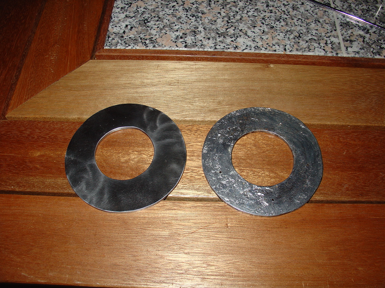
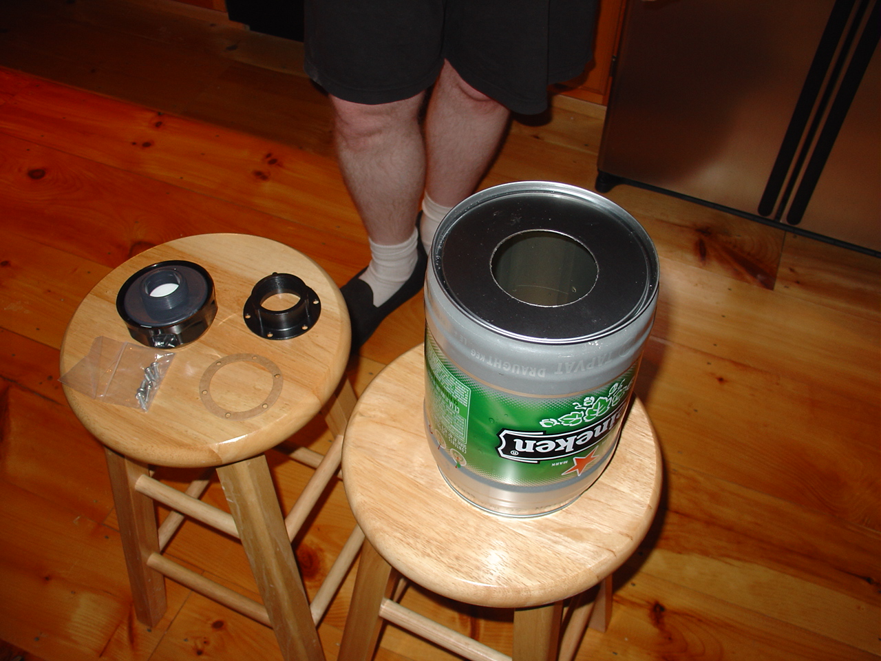
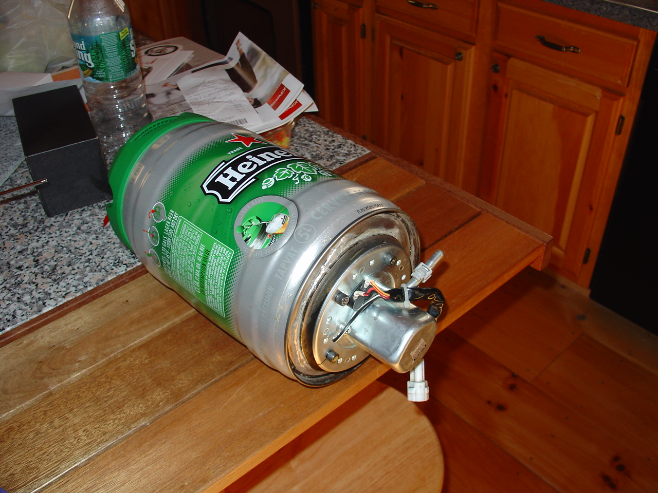
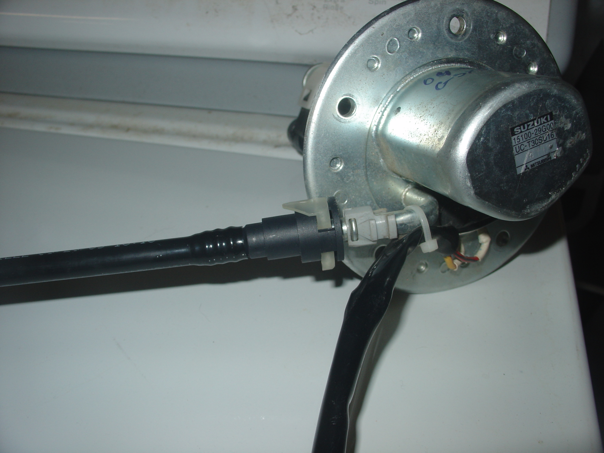
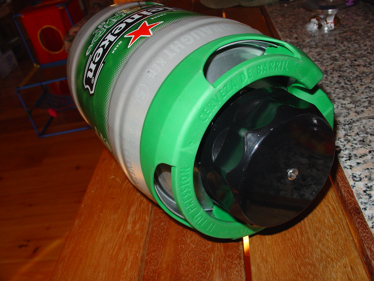
Phase 1, Fuel first My first goal is to get it running with fuel only, with a plan for ignition later. I have several decisions that need to be made before I can think about starting. Missing items include injector bung, tach signal, throttle position sensor, intake air temp sensor, engine temp, ECU and fuel pump. The motor I'm using includes a 12VDC alternator, so I'm good for the battery requirements. I first started with the fuel tank/fuel pump. I found a motorcycle fuel pump on e-bay that included the regulator and did not require a return line. This pump drew a bit over 4 amps at 13.37 V and produced about 50psig. It's a Suzuki 15100-29G00 UC-T30SU16 and includes a Mitsubishi stamp as well. Cost about $60 on e-bay. When I got it, I found it was originally mounted to a plate, and used an o-ring to seal the gas inside the tank. I didn't have the plate, so I fabricated a piece of steal with the help of a friend. I used .25in thick cold roll and cut it into a washer shape via flame and eye ball. I used the pump as a guide and drilled and tapped the three bolt holes into this heavy washer. Now I have a plate that allows the o-ring to seal against the tank. I threaded some bolts in the three holes, and soldered it to the bottom of a small keg. //Note: do test runs with the solder before you attempt to solder steel, many solders only work for specific metals//. I had steal on steal, so I was able to get by with normal lead tin rosin core type solder. I soldered this in a bucket of water to prevent the non soldered area from getting to hot by the propane torch. The bolts kept the solder of the the holes which now allows me to mount and seal the fuel pump to the keg. I use a hydraulic fill cap as my gas tank. It include a filtered vent, so I don't have to worry about pressure build up. It's also quite large in diameter, which prevents spills during filling.
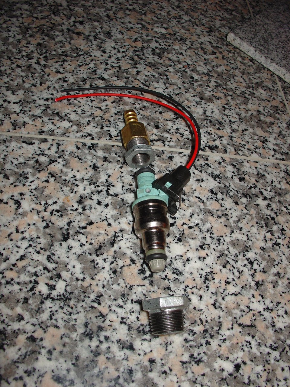
I choose two fuel injectors to try. One is a Festiva injector, the other is a Bosh injector. I obtained them from injectors4u.com for about $25 ea. The purple injector numbered 195500-2110 drew about 1 amp DC and filled 200ml in 1.49. (un seconds? or 1min 49 sec?) The other blue injector from BOSH was numbered 0280-150-993 also drew about 1 amp and filled 200ml in 1.41. Both these injectors have flow rates that are quite low and will likely work for this application. I ran the on-line calculators to find injectors that should work for both idle and WOT.
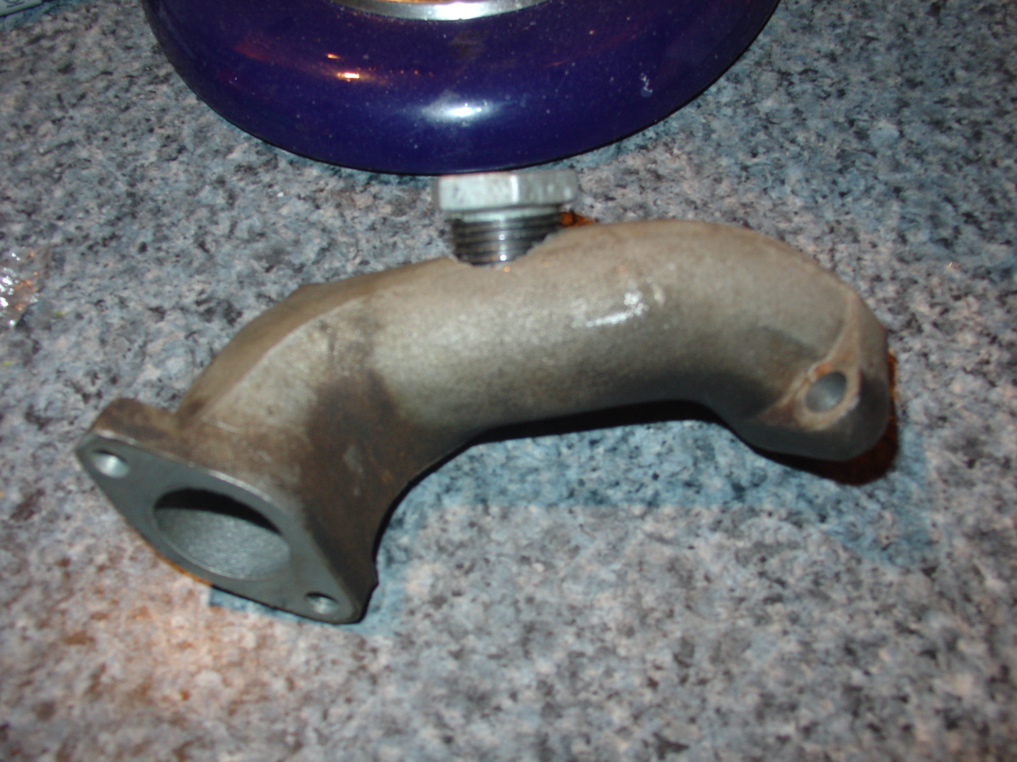
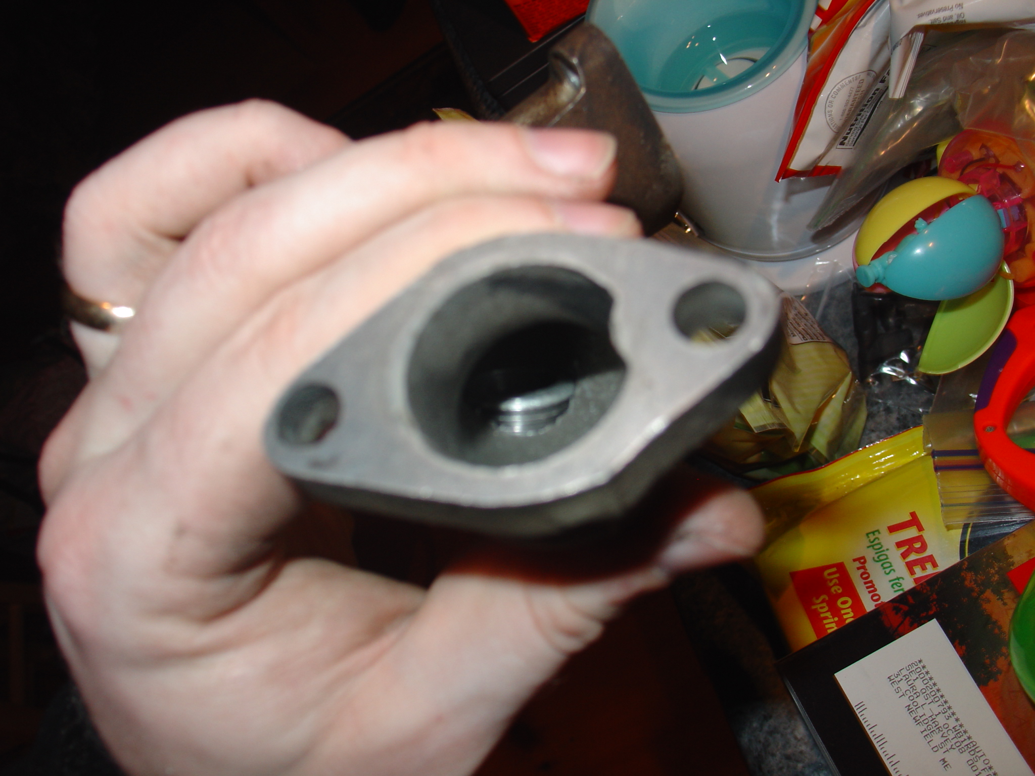
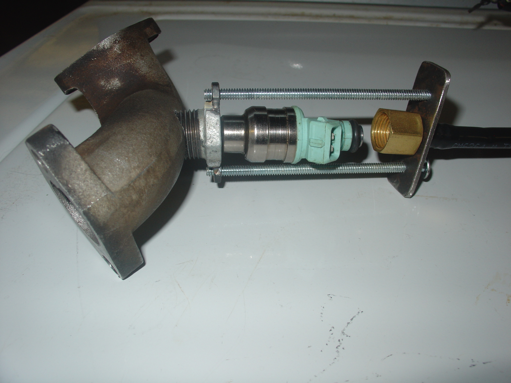
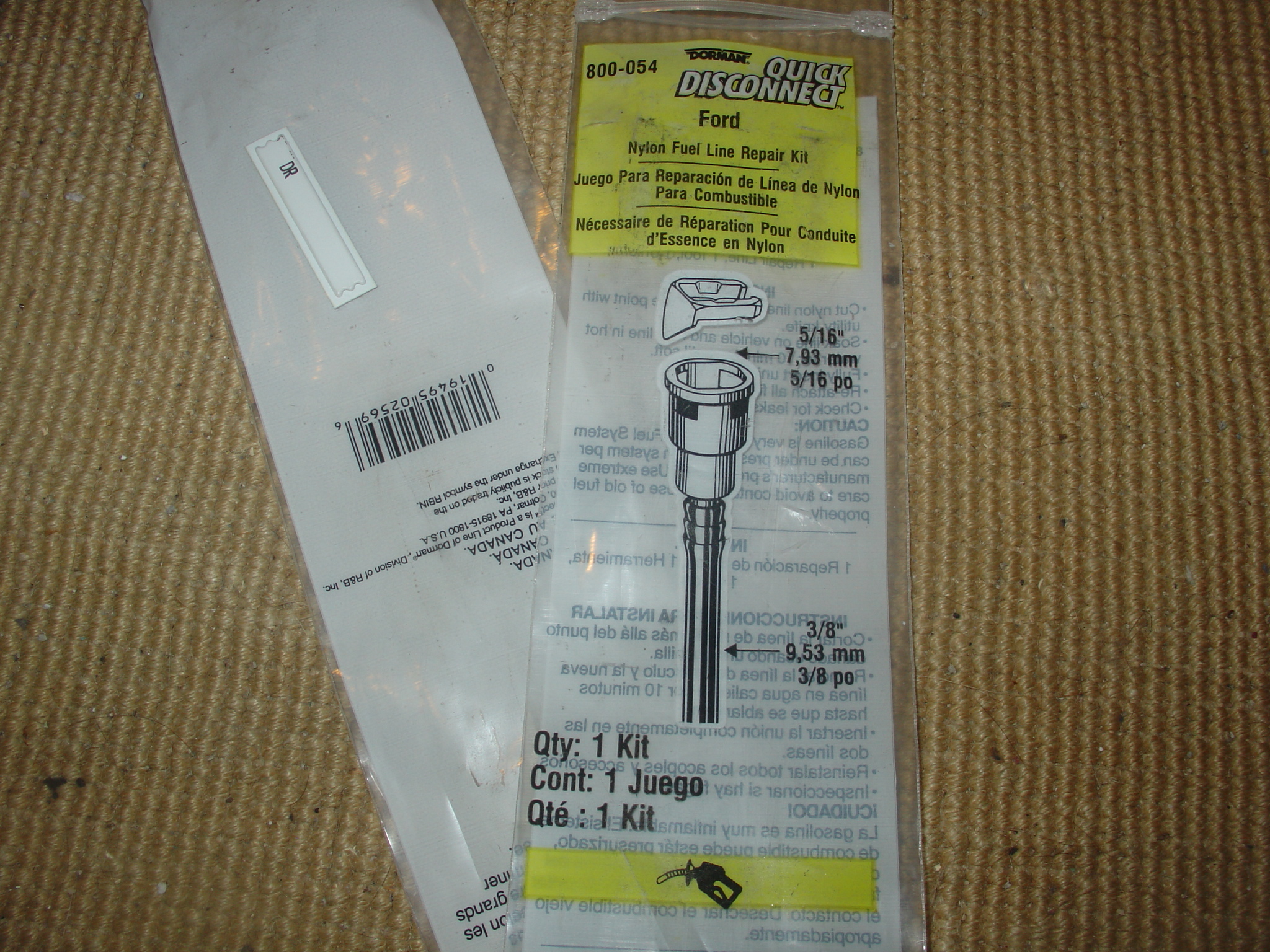
With injectors in hand, I started on the bung. In the hardware store's plumbing dept, I found pipe hardware that had a threaded OD and ID that allowed me to bore ID's with two drills making the pipe adapter a bung. I did the same for the other end of the injector, making an adapter that terminates as standard hardware. I then held the two together with ??? (not done yet round 1 will likely be mechanics wire).
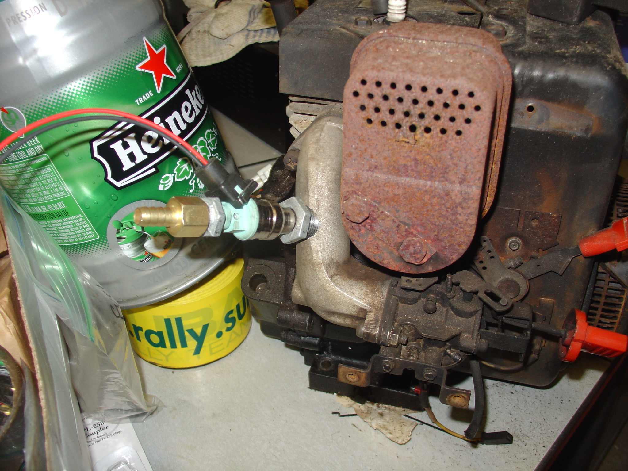
I took off the carb ducting, drilled a hole in it and threaded in the manufactured bung. I used a pipe tap to cut the threads after I cut the hole in the ducting. These taps can be obtained at mcmastercarr. My tap was very similar to McMaster #8328A15. The top of the injector uses a 3/8 NPT coupler and barb fitting. I can drill out the NPT step down coupler to make the injector. When drilled/reamed for the standard .550 in dia injector bung, the wall thickness on this NPT adapter is about .032 in thick. So you have to be really close to on center. This has been quite a bear for me with my worn out drill press. I may switch to a block of alum from McMastercarr and drill several hoels in then use a male thread barb fitting. Now I have the pump and injector, I need to work on the temp sensors. I don't have the hot wire sensor that cars typically have, and I can't add one because I'm stressing the alternator. So to keep the electrical requirements down, I decided to use a thermistor. I found Murata's NTSD0XH103EE1B0 Mouse 81-NTSD0XH103EE1B0. I created an xls sheet to look at the voltage out of the resistor divider. Found here. this shows a fairly linear curve between 0 and 5V on a temp range from -15c to 125c. This should work for both intake air, and engine temperature. However note the power consumed is a bit high for this device around 120. The use of a switch to duty cycle the sensor is probably a good idea. If not it will definitely cause the sensor to self heat, and may cause a short life or erroneous reading.
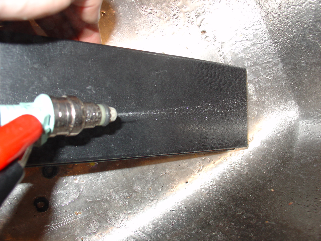
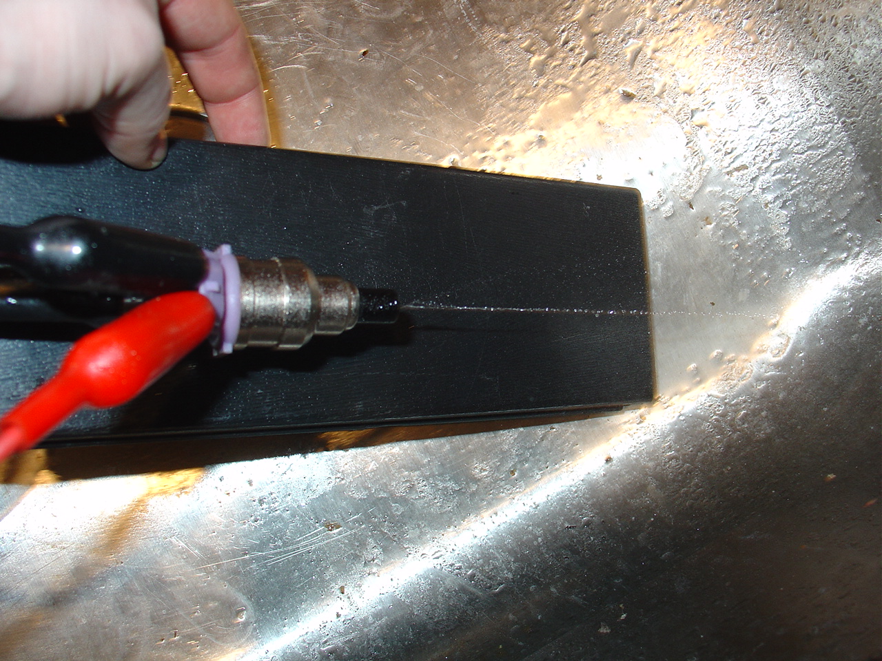
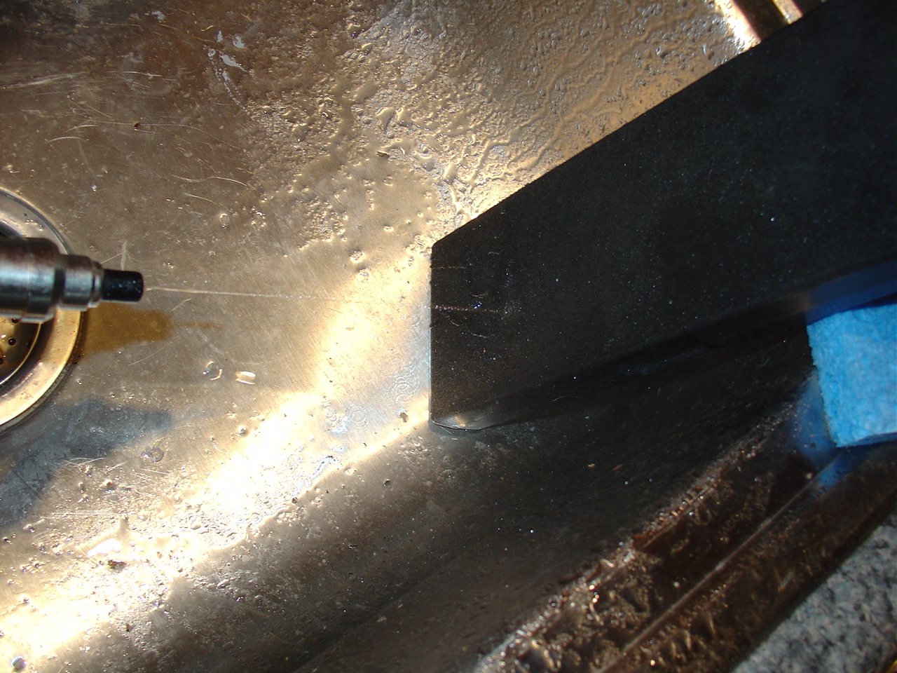
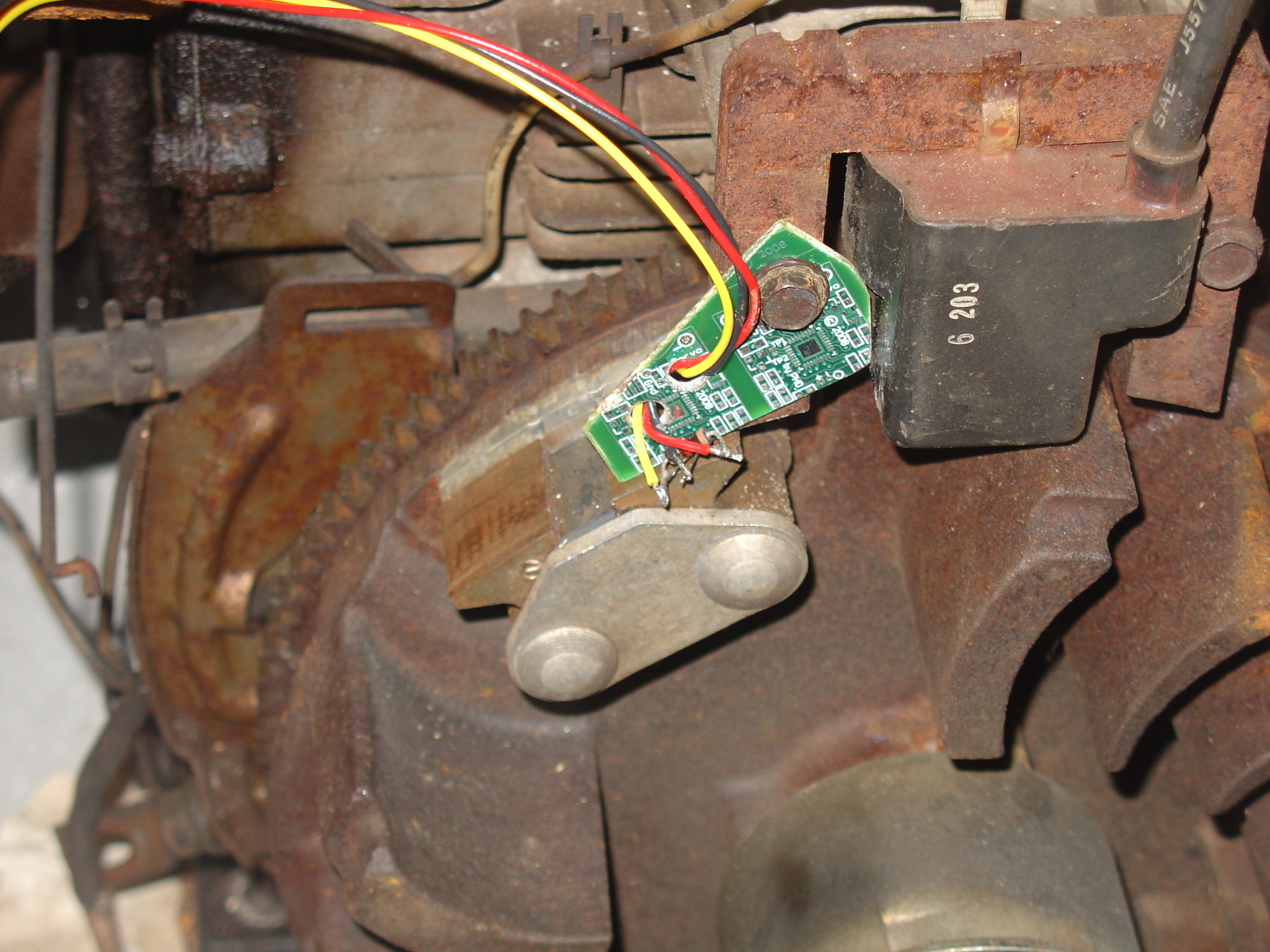
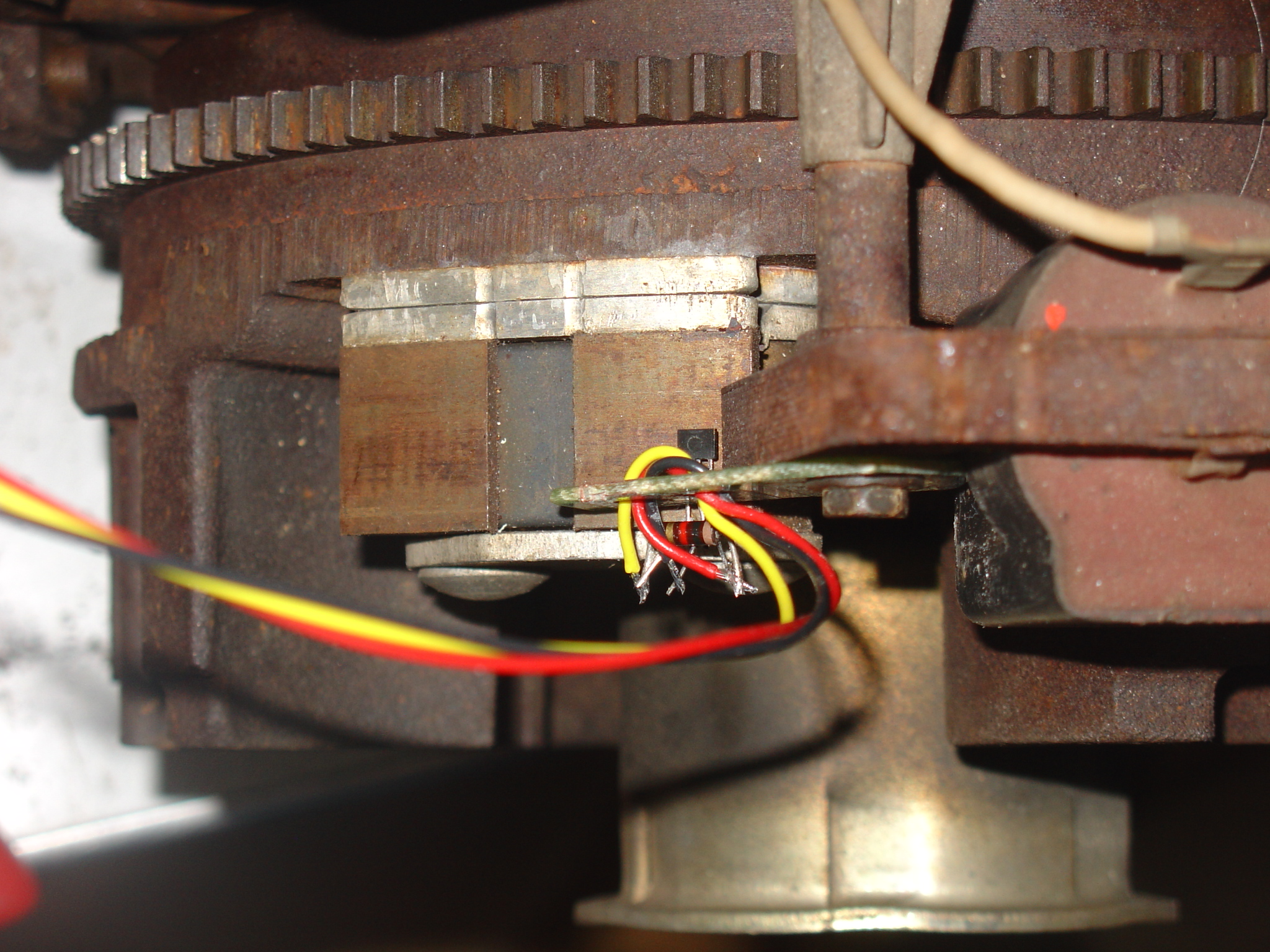
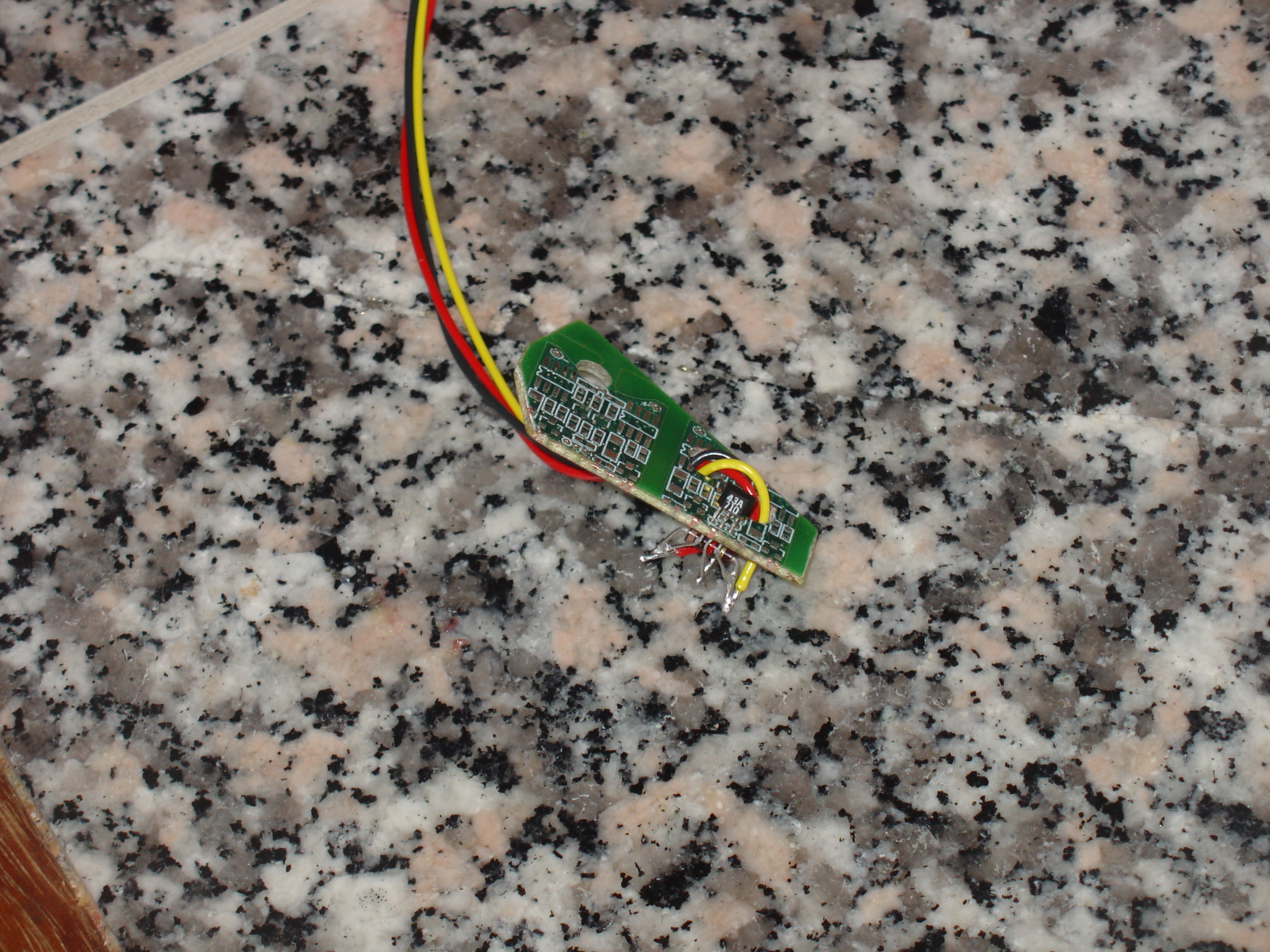
I found a hall sensor Honeywell's SS443A Digikey's 480-2002-ND, when mounted near the flywheel, I get a good tack signal. I used a piece of an old PCB for mounting it, and I put a bias resistor across the leads. The sensor switched to gnd, so I put the 1k ohm bias between +5 and the signal. For this round I can mount it anywhere, TDC isn't' important. I did get it located at about 10 to 15 degree's before TDC. Throttle position, is easy, You only run a snowblower at WOT and idle. There is a kill switch in the throttle lever. I can use it to indicate WOT vs idle, If I need, I can add a resistor with an intermediate contact point for half throttle, but for now, I plan on two states. |
||||||||||||||||||
Phase 2, Ignition Remember to add ignition stuff when you do the ignition stuff. When you trigger at TDC, you have to assume the RPM is constant and make your best guess when to fire. The closer you get the sensor pickup to the fire point, the less guessing your doing. What is the best placement of the hall sensor? Hmmm. Note, what is the best placement for the hall sensor? Advance is sometimes up to 15° to 20°, the coil charge time is ? at up to 16,000 RPM that's 10 nano sec / degree. 8 hp max rpm is 3000. I'm guessing around 30° to 35° should work well. Hmmm, you can guess on the coil charge, just guess high. That might get this to 25°, Hmmmm. |

Last update Feb 22, 2008 E-mail web@jaredharvey.com