 |
FEA Magnetic encoder Analysis by Jared
Magnetic encoder FEA
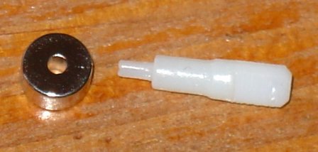
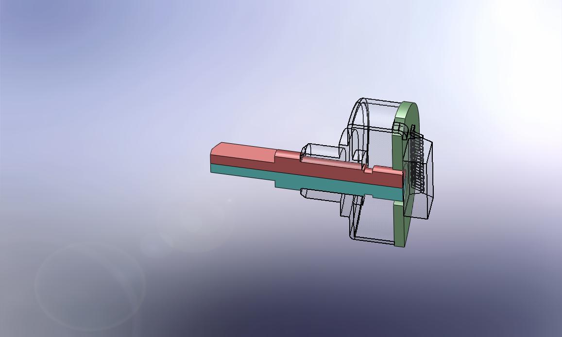
To the left are some pictures of the final encoder. It consists of a
custom magnet and a rapid prototyped SLA shaft. The SLA shaft reduced
machining cost greatly, and allowed for a much easier assembly. This encoder allows several hundred RPM and absolute position, with better than .1 degrees of angular resolution. All that and the parts cost about $10.
|
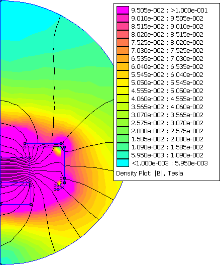
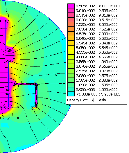
| The vendor of the magnetic encoder chip,
recommends a magnet for use with their chips. I modeled that magnet
both mechanically and magnetically for the base of my design. To the
left are some pictures showing how this recommended magnet would fit
the encoder case. Click the picture or the [+] to see a larger copy of
the picture. The lower picture shows the flux density indicating how strong the field is when it's penetrating the encoder chip. This give me a flux density to try and maintain in my final design. A weaker flux density would likely cause inaccuracies in the sensed position, as well as allow outside fields to raise the noise floor. Both bad things that need to be prevented for a good quality encoder. |
|
This shows my first attempt at this
design. I did this design before I knew about FEMM, I designed it
completely based on gut feel. I sure am glad I did the FEA. This could
have cost me a pretty penny if I had gone with it. I had thought that
even though my magnet was a smaller diameter, the extra length would
make the flux a near equivalent of the above vendor recommendation. Boy
was I wrong. This design used a custom magnet that was indented to replace the original shaft. This shaft had a feature to align the encode chip and circuit board. The design intent here should have allowed for just about anybody to modify an off the shelf servo. However it simply wouldn't have worked. |
|
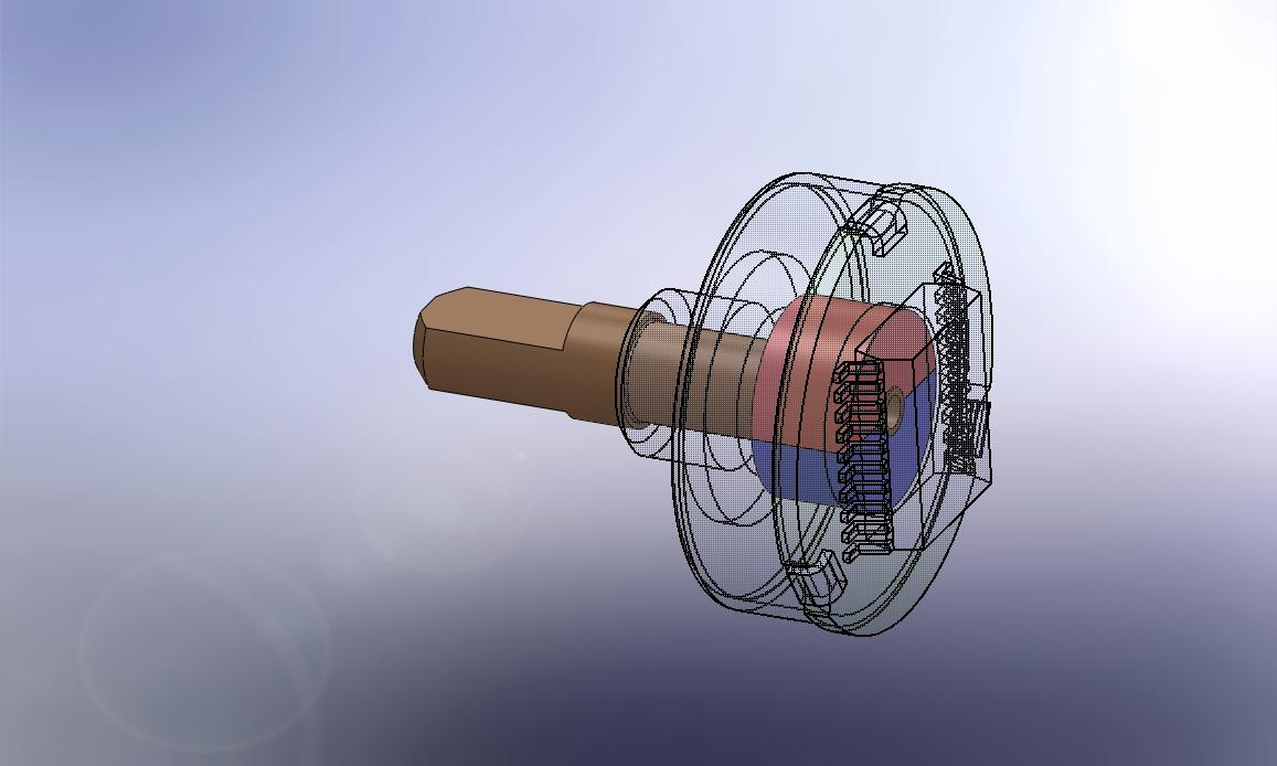
This is the final design. I did an
asymmetrical FEA with FEMM. This allowed me to confirm the magnet flux
should be similar to what I saw with the vendor recommended magnet.
This prediction indicates this magnet is going to be strong enough to
allow the chip to function correctly. The chip will report if the flux
field is to strong or too weak, and the FEA landed it right in the
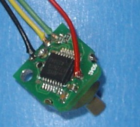
middle on the first prototype, not to strong and not to weak. This design uses a custom magnetic ring. The shaft is made via SLA rapid prototype plastic machine, and the PCB incorporates an alignment mechanism. Such that no expensive alignment equipment is required, and the parts can be assembled very rapidly and cost effectively. |
|
 [+]
[+] [+]
[+] [+]
[+] [+]
[+] [+]
[+] [+]
[+]Last update Jun 12, 2009 E-mail web@jaredharvey.com