good points,
kb1gtt wrote:
About the max 9926 chip, I see what you are saying. In the below on page 3 it notes the "Watchdog Timeout for Adaptive" is typically 85mS but could be as much as 125mS or as little as 45mS. In the picture you posted, I'm assuming that's your single tooth wheel, running at 480RPM, which is pulsing about 125mS. Pulses which happens that slow will cause the adaptive window to reset, and it will reset to 33% from the peak to peak voltage in that window, with a minimum around 5 to 10 mV. This is causing a small amount of noise to cause a false trigger. If you were to rotate the engine faster, it would catch a pulse in the window and you'd be all set. As well I expect the 4 tooth wheel would be pulsing once every 31.25mS, so the 4 tooth wheel would be OK, but the CAM is causing some noise issues as lower cranking RPMs.
http://datasheets.maximintegrated.com/en/ds/MAX9924-MAX9927.pdf
I expect you'll have that same issue with the polarity flipped or not.
I arrived at the same conclusion regarding the source of the false triggers, however I wasn't able to reproduce the false triggers with the polarity flipped. My conclusion was that it was because the MAX9926 is detecting the signal going above a positive threshold. With the polarity flipped the signal ramps negative before flipping positive, so no false triggers are produced.
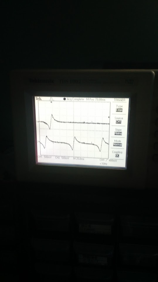
kb1gtt wrote:It looks like you are using your scope with GND strap to measure a differential signal, as well I don't expect a 2.5Vp-p signal for such a low RPM. I fear your VR may be a hot one, or your scope might be reading incorrectly. Perhaps the 10X vs 1X scale was not correct. I see it was on the 10X setting for channel 2. Can I get a verification the channel 1 was really measuring 2.5Vp-p? If it is, can you crank you drill up to your max RPM and see what kind of voltages you get then? You may need to install a loading resistor. I expect you currently do not have R111 or R112 installed. You may need that if your VR is supper hot. Also did you use the 5k's noted for R102, 107, etc? Where are you measuring your VR signal, I'm assuming you're measuring the VR directly. If so remember the max9926 will be seeing that signal after the resistors, so the max chip is likely seeing a much lower voltage than what is on the screen. As well you were probably only looking at one side of the VR, not the differential signal that the max chip is seeing.
Also about that 2.5V DC offset, this tells me you have the GND strap connected to the MCU negative or chassis GND. Be careful doing this, as your scope GND strap is connected to your wall outlet GND wire. You can easily get GND loop issues that often cause problems. You'll likely be best off taking that measurement with ch1 on one side and ch2 on the other side with the GND straps connected together. This makes your scope a differential sensor instead of single ended, and prevents GND loop issues. Then if you connect ch1 to one side of R111 an ch2 to the other side of R111 to ch2, then you'll see what the max chip is seeing. But beware do not connect your GND wire to either side of the max chip directly, it will short your 2.5V bias to GND which may break something.
Good point regarding ground loops from the scope probe ground leads. In this case the rusEFI was floating (USB powered from my laptop which doesn't have a ground lead on it's power adapter). I think the scope scales are correct, based on the 2.5V bias from grounding the probe to uC ground. You are correct I am not producing a proper differential measurement of the VR sensor, however it seems that the MAX9926 holds the -ve VR signal at the bias voltage (2.5V), so the signal shown is correct with the exception of the 2.5V offset.
I agree the amplitude of the VR signal looks high for that RPM. I did not populate R111,112, and R102-110 are all 5k each. What is the max signal allowable by the max 9926? I was measuring with the probe ground lead connected to the uC ground, and the probe connected directly to the VR sensor. Directly connecting the scope probe to the positive input side of R111 would give a more accurate result since it would show the effect of the input low pass filter.
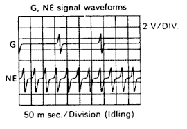
After a quick google search (the image above is from the original application of my sensor setup), it looks like most VR sensor signals show the signal ramping positive before flipping negative (opposite to what I have been proposing). This suggests I have been wrong, and that this is an issue with my system, and I need to fix my setup. I think I can do a couple things to reduce the amplitude of the signal between pulses so it stays below the default threshold level:
1) add R111 and R112 to reduce the amplitude of the signal. I think this is the real solution. Since the signal response is so large, I can reduce it significantly and keep it below the threshold, without compromising the ability of the circuit to detect the tooth at low RPM.
2)
I can increase the gap between the sensor and the tooth.... on second thought I don't think this is a good idea. It will decrease the signal peak amplitude, but won't decrease the between-tooth signal amplitude, which is what is currently causing the problem.
kb1gtt wrote:
Russian, how hard is it to make the CAM signal less sensitive, such that it only cares about a CAM pulse +/- 45 degrees from the 4 tooth wheel? If that can be done in software, it would allow him to accurately detect the low RPM cranking situations. If not then it will likely be a much harder item to resolve in hardware. Is there any chance the CAM is already less sensitive like that? Would this extra pulse on the CAM at low RPM cause a problem with the wheel decoder?
Personally I don't think this is a good idea. I think at this point you are probably best to require solid hardware, at least while the firmware is still being developed/proven.
-Matt