Just assembled a Frankenso board and trying to decode my Subaru VR camshaft and crankshaft sensors. Not going well so far - not sure what to do next? I do not have an oscilloscope.
The signal is somewhat close to how it should looks (7 tooth on cam and 6 tooth on crank) but have plenty of noise.
you'd better clarify what you mean by 'made things worse'. As far as I got, removing the w1002-w1003 resulted in some noise on the table. No tests have been performed on car. Besides, I can't see any reports about removing R111&R112
Is this the same-ish as my little red suby? I was having a bunch of noise getting into the VR signals, then I ran out of time to track it down. Mine is a 98 with a 2002 WRX smashed into it, with lots of questionable wiring. If I had the time, I would tear out all the wiring and start putting stuff in from scratch. However, rumble groan moan, time is a problem.
My frustrations were that I was getting electrical noise coupling in from some other wiring. This was causing false pulses, which was caused by the analog signal having blips. I could see the noise regularly, but it only causes false pulses when those pulses were close to the cross over point.
How is this wired? I'm assuming OEM wiring. Does the OEM use a common GND wire or does it run 2 wires that are twisted down to the sensor? Do we have a schematic for this vehicle? I might be able to help find sources of noise. I believe if we can remove the electrical noise, we can get proper pulses.
Can we get a capture of the analog signal with a scope?
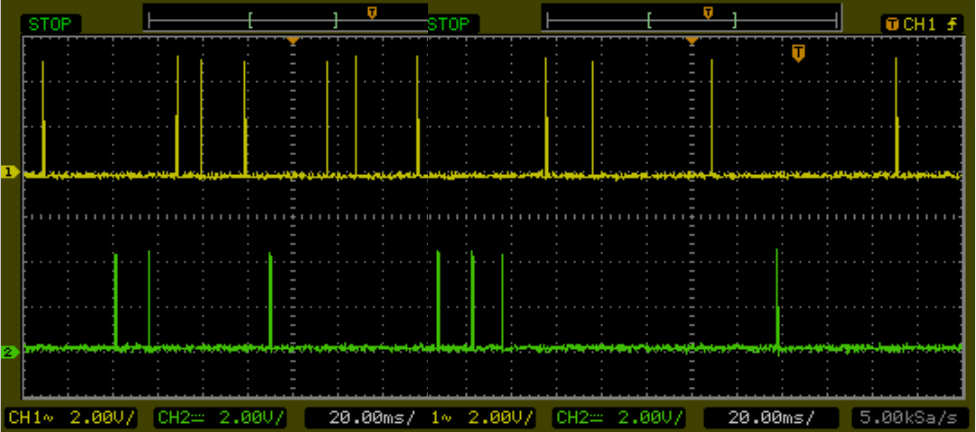
Paraller to stock ECU we get great signal while running but not so great signal while cranking. Both times hooked up to stock ECU so whatever electrical on the ECU side is the same.
At low RPM, the signal is very small, so a small noise becomes a problem. However at higher RPM your VR signal is larger than the noise, so problem goes away.
You say while cranking the signal is still blah for both, but apparently the stock ECU is able to decode well enough to get started and operate correctly. Perhaps a low pass filter which removes higher frequency noise might be the solution. Another thing to consider, by measuring between the wires on the stock ECU we could get an idea for what they have for an impedance. It might show that we have 5kohms or something like that. Then if we reproduce that same impedance on our input circuit, it would likely be less susceptible to noise.
I should figure out a way to measure the impedance of a VR, such that we can know the impedance. You get the most watts and lowest noise floor when the VR impedance matches the capturing circuit's impedance.
That's sounds about right, and I wonder if he got it running. I was thinking that if I measured the VR's characteristics I could then tune the impedance, filter cut off etc of the MAX's fronted. I guess I could run the DSO quad's VNA on the OEM to get the OEM ecu's characteristics. I did not know about the 85mS zero crossing timeout think. Perhaps this would be a good application for the ones with ECU controlled thresholds instead of the autotune thresholds. Or perhaps I should just use a 24V battery to double the cranking speed from 180 to 360 RPM
This may have been mentioned in the megasquirt post but if memory serves either the dual VR conditioner they have or a 2.2k resistor inline with the crank sensor seems to work.
What's that dual thing? It has nothing to do with crank. It's cam, and it's rotating too slowly in the very beginning that the fixed hysteresis (watchdog?) time is still too short.
puff wrote:What's that dual thing? It has nothing to do with crank. It's cam, and it's rotating too slowly in the very beginning that the fixed hysteresis (watchdog?) time is still too short.
The MAX9926 is configured for an adaptive threshold. The once every 85mS (possibly up to 140mS) the threshold voltage is set to 33% of the max voltage seen in that window. The min it can set the threshold is 15mV. When cranking, this Subaru wheel, and other low tooth wheels, it won't see one tooth in that window, so it sets the threshold to the min at 15mV. Now when a tooth comes along it might generate a pulse of like 500mV which would certainly be enough to register a output. While the threshold could probably be set to something like 160mV, the auto adaption sets it to 15mV. This means that a small amount of noise will trigger a pulse on the output. If you have more teeth, this is not a problem as the adaptive will adjust the threshold to 160mV and your all set. However the lack of teeth cause the threshold to be set to 15mV. So to solve the problem, someone decided to add a resistor across the VR, such that the signal seen at the MAX chip is more like 45mV instead of 500mV.
I need to get out in the garage, then start cranking over the suby, and then add a resistor until I dampen the pulses from the suby VR to about 45mV. Based on that forum post, I'd start at about 2.2k and see how big the pules are.