My board arrived on Friday (after some battles with parcel force, apparently you cant pay customs the same day as it clears customs and I mysteriously asked for a later delivery.

)
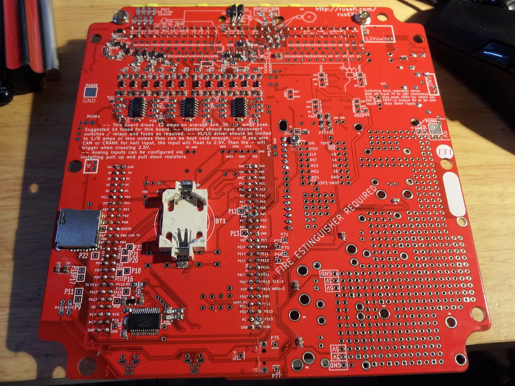
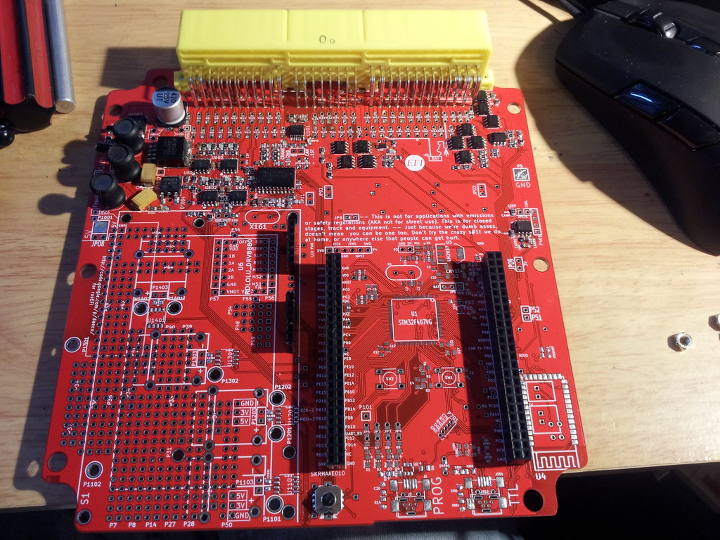
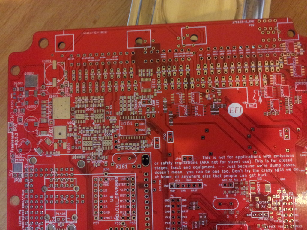
I have started populating the board so I will start dropping details into this thread, for now each post is going to be the brief notes that I am keeping as I go but I will add photos of the stages to the posts once I am further along. There may also be the odd question mark in here which hopefully we can resolve as we go along, this is going to be warts and all.
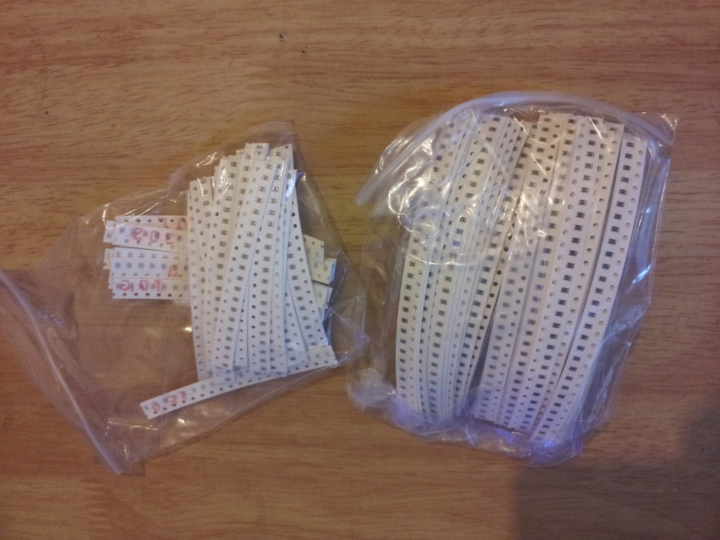
Before starting order 0805 package 10uF 10v and 4.7uF 50v capacitors as these are not in the basic SMT kit.
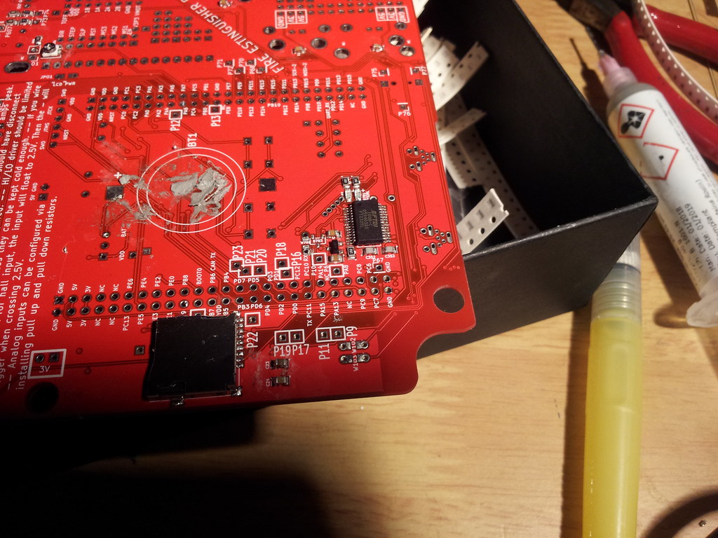
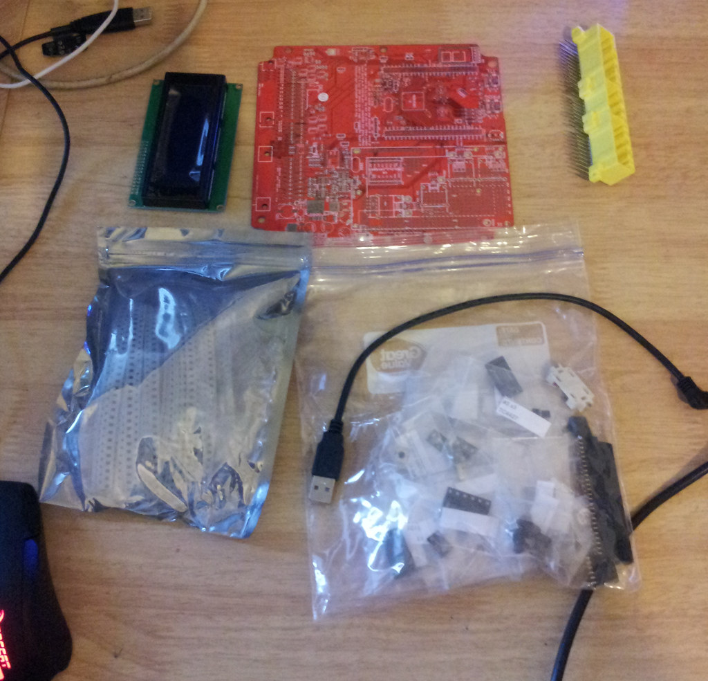
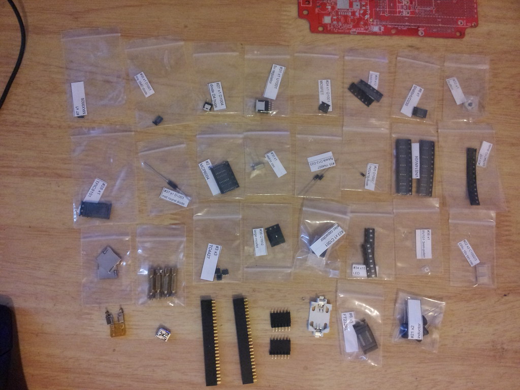
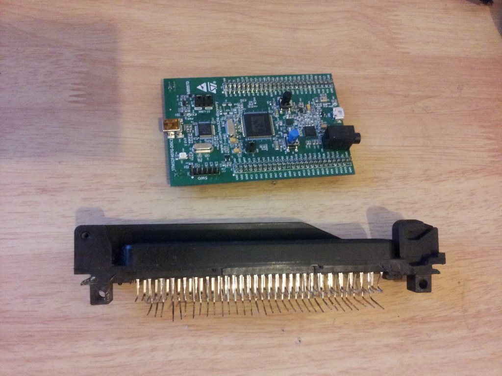
[Some photos of the kit as delivered. Note - Black plug is from a 316 ECU and not part of the kit. ]
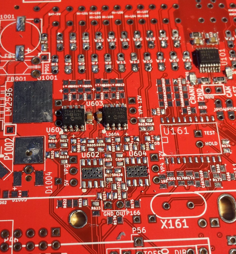
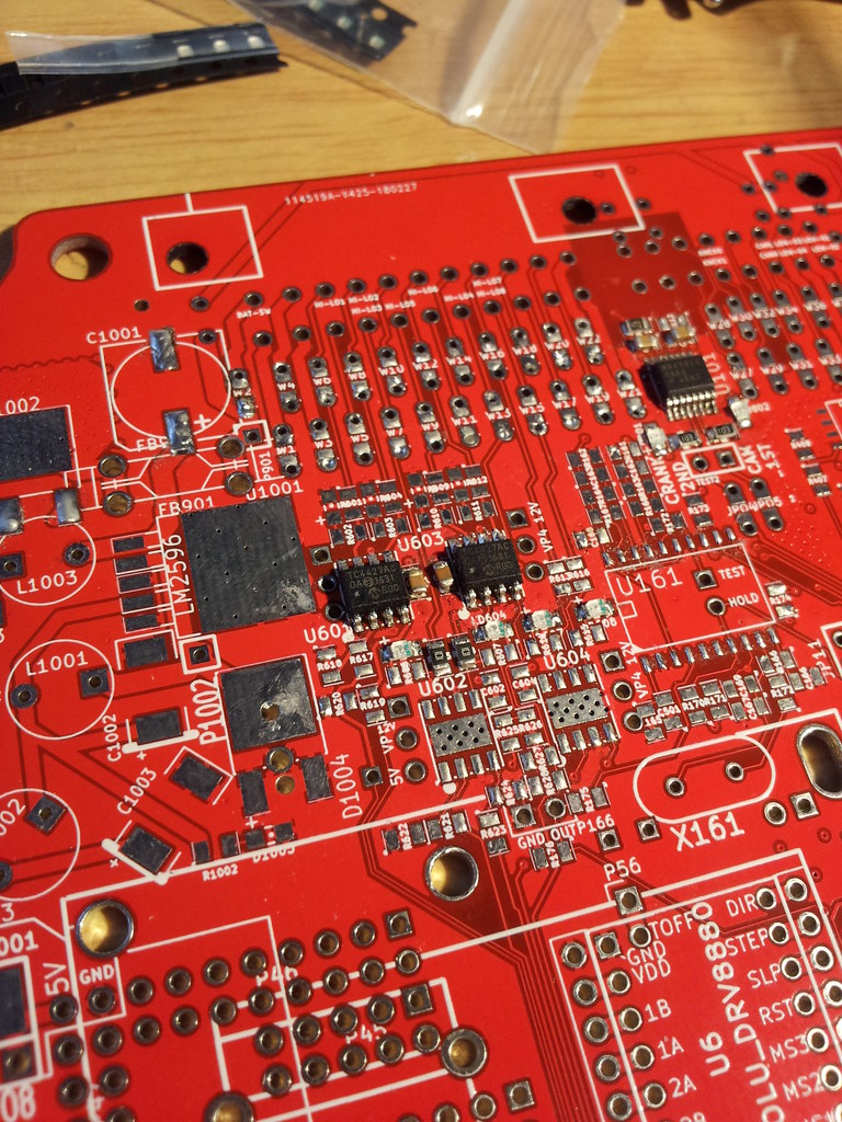
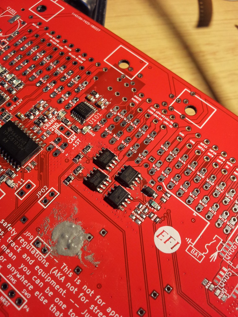
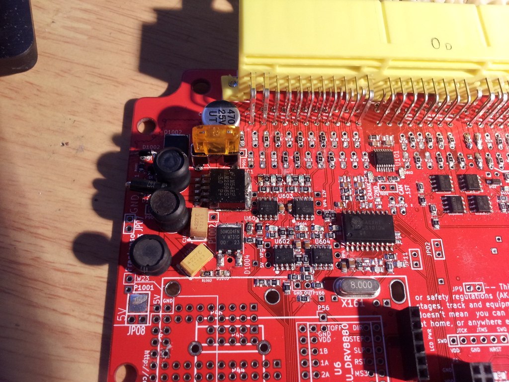
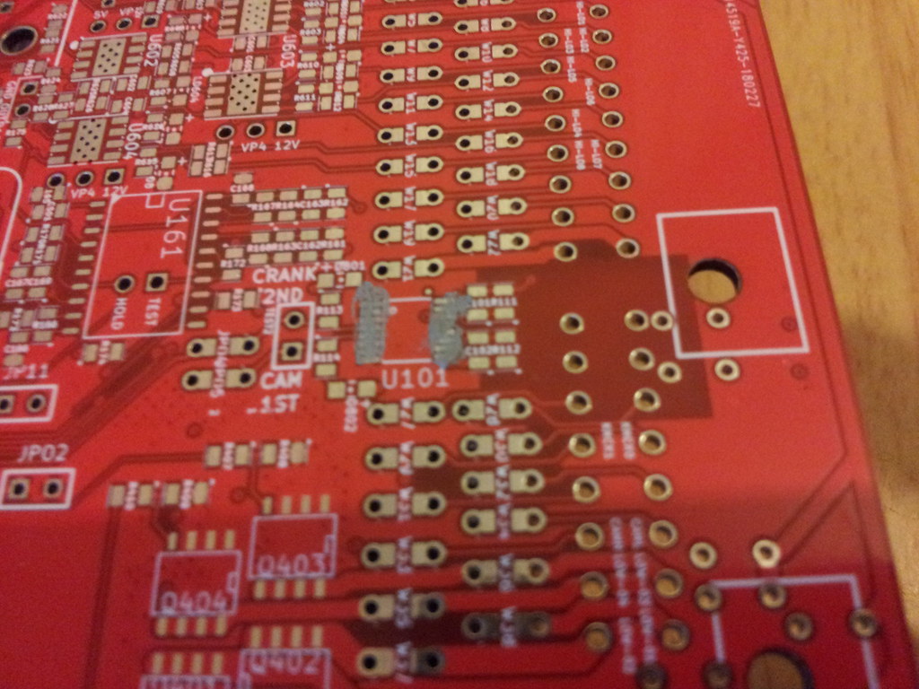
I went for the MAX9926 circuit first as it is supposed to be the hardest and if I was going to screw this up I may as well only screw up a board and 1 chip.

I can confirm it is the hardest.
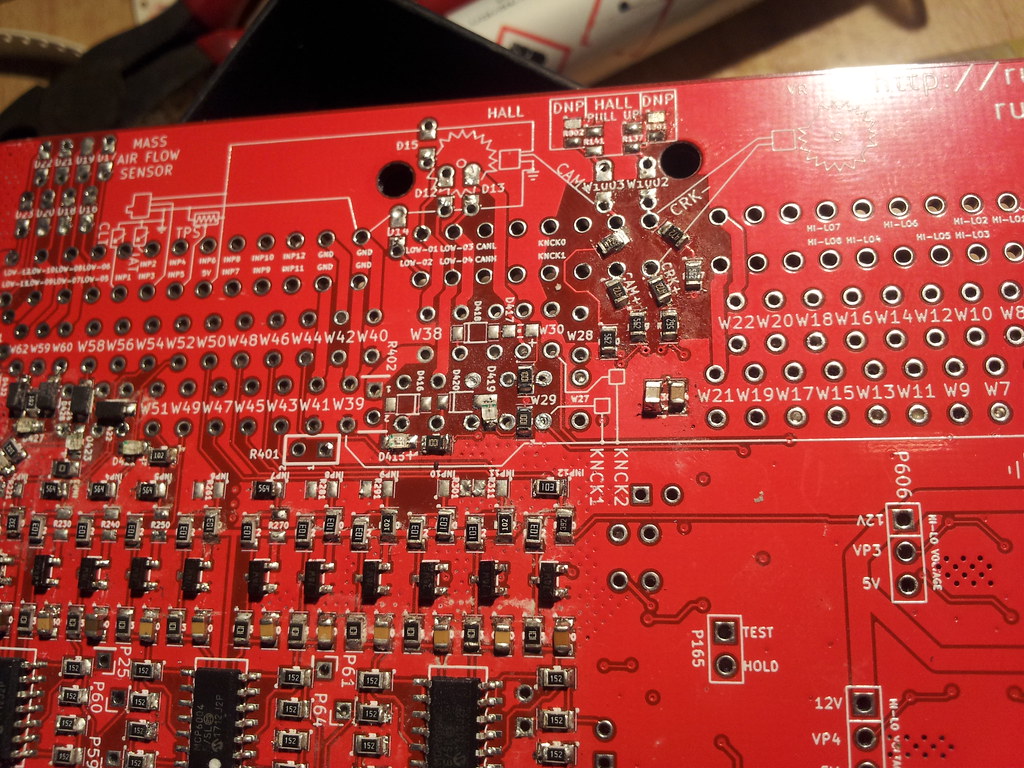
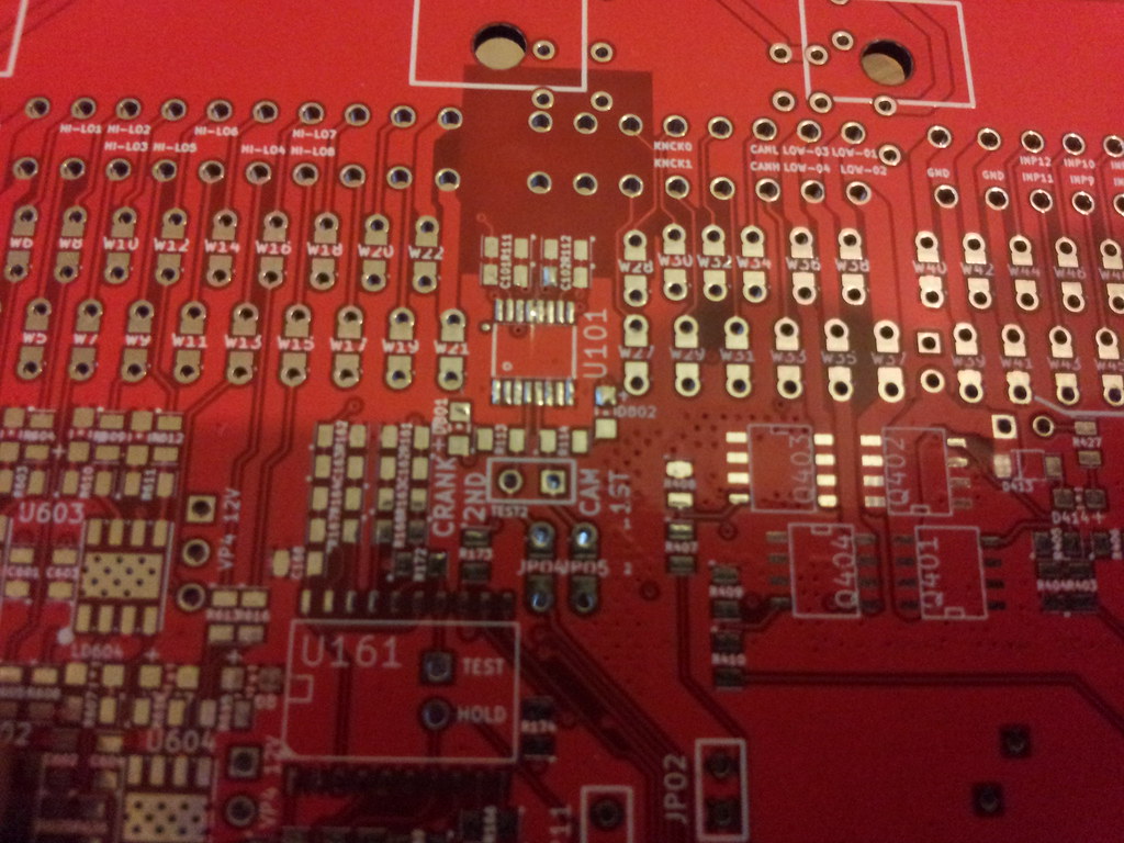
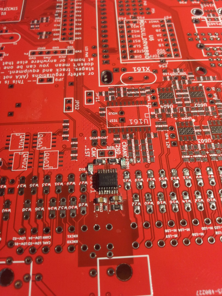
put max9926 down first, pins are very easy to bridge but several pins are actually connected to ground plane.
left pins 11,12,13 bridged on mine as they are all connected to ground and thus the bridges make no difference?
https://datasheets.maximintegrated.com/en/ds/MAX9924-MAX9927.pdf
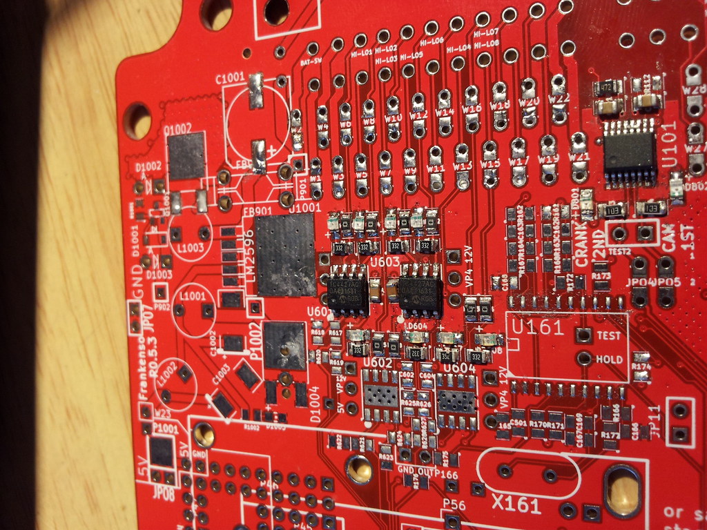
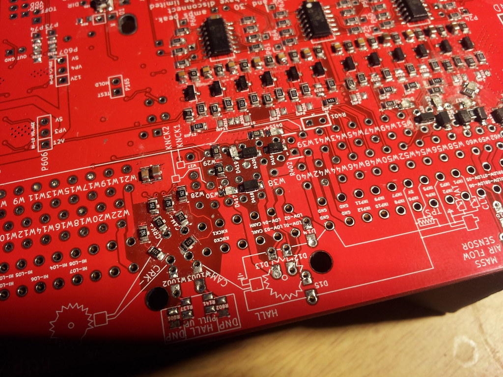
[Paste and tinning. Note the marks where I tried to seperate what I thought were bridged pins and they had continuity only to spot later they were actually connected via the traces

]
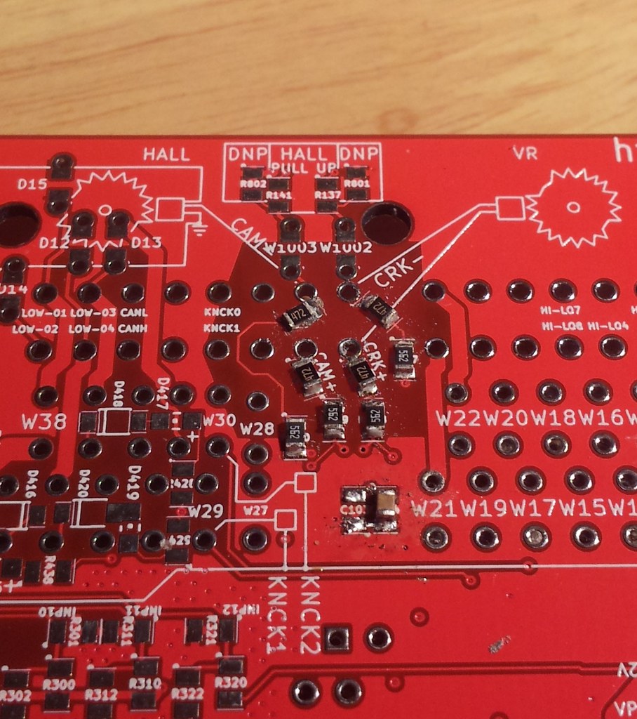
C101 and C102 - marked 102 (10*100 or 10+"00")
https://www.radio-electronics.com/info/data/capacitor/capacitor-markings.php
https://circuitdigest.com/calculators/capacitor-value-code-calculator
R111 + R112 = 4K7 strip = 4700 ohms = (472) on resistor - might not be needed unless signal is bad, BMW M50TU = 1x VR 1x Hall
R113 + R114 = 10k ohms (103)
D801 + 802 LED - Line to -ve little dash points to positive, be careful of LED orientation, check ground with meter if needed
C103 - 10 uF (added after photos due to not being in the kit, see note about ordering these at the start).
R102 R103 R104 R106 VR input primary - 4700 ohm (472)
R107 R108 R109 R110 VR input secondary - 5600 ohm (562)
W1003 - do i need to put 0 ohm res in the JMP?
Need to add pull up or down to cam VR to suit the BMW M50TU cam sensor
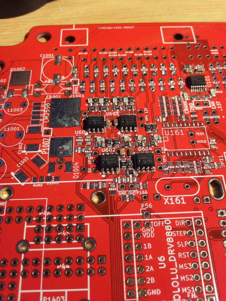
Also one other question, some of these chips have bare pads on the board to solder down pads under the chips, obviously for heat reasons but so far none of the chips have pads on the bottom, they are all plastic so, uhhh, no can solder?
I have left them solder free unless the chip has a contact pad to solder down, I assume this is the correct choice?