

I'm tested one board without FET,
and have same result .. as you can see on videos ..
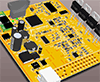
This LED wiring for heater activity is wrong ..
look here also .. https://rusefi.com/forum/viewtopic.php?f=4&t=1052&start=180#p33371
DEAD DESIGN rusEfi own wide band controller board add-on using CJ125
-
JRD McLAREN
- contributor

- Posts: 442
- Joined: Mon Mar 04, 2019 10:19 pm
- Location: Slovakia

Re: rusEfi own wide band controller board add-on using CJ125
Last edited by JRD McLAREN on Fri Jun 14, 2019 10:02 am, edited 1 time in total.
.. some Proteus and microRusEFI for sale in Europe ..
-
JRD McLAREN
- contributor
- Posts: 442
- Joined: Mon Mar 04, 2019 10:19 pm
- Location: Slovakia
Re: CJ125 board
Is not problem to "make some heat on heater" ...
Is the problem for CJ125 chip, to measure heater resistance correctly...
(and started to work, in my case)
.. some Proteus and microRusEFI for sale in Europe ..
-
JRD McLAREN
- contributor
- Posts: 442
- Joined: Mon Mar 04, 2019 10:19 pm
- Location: Slovakia
Re: rusEfi own wide band controller board add-on using CJ125
OK .. small victory ..
It started to work, after cranking ...
but it cut-off, when heater dc reach 90%...
..and console log is full of unknown numbers .. for me..
Any advice ..??
Can anybody post me, "any range" of working UA and UR values..??
Is (any) switching between LSU4.2 or LSU4.9 needed ..??
..or it is automatic ..??
You do not have the required permissions to view the files attached to this post.
.. some Proteus and microRusEFI for sale in Europe ..
-
AndreyB

- Site Admin
- Posts: 14809
- Joined: Wed Aug 28, 2013 1:28 am
- Location: Jersey City
- Github Username: rusefillc
Re: rusEfi own wide band controller board add-on using CJ125
OMG, we've forgot to make the checkbox visible in Tuner Studio. Here you are - https://github.com/rusefi/rusefi/commit/43acf4c3fc740fb204a3f89d848cdd3470ff115cJRD McLAREN wrote: ↑Fri Jun 14, 2019 5:55 pmIs (any) switching between LSU4.2 or LSU4.9 needed ..??
..or it is automatic ..??
also there are resistors on the PCB. So, by default it's 4.2, now with the switch you can change to 4.9
Very limited telepathic abilities - please post logs & tunes where appropriate - http://rusefi.com/s/questions
Always looking for C/C++/Java/PHP developers! Please help us see https://rusefi.com/s/howtocontribute
Always looking for C/C++/Java/PHP developers! Please help us see https://rusefi.com/s/howtocontribute
-
AndreyB
- Site Admin
- Posts: 14809
- Joined: Wed Aug 28, 2013 1:28 am
- Location: Jersey City
- Github Username: rusefillc
Re: rusEfi own wide band controller board add-on using CJ125
I have some of Matt's logs at https://github.com/rusefi/rusefi_documentation/tree/master/overview/wbo - that's 4.9 I believe
Very limited telepathic abilities - please post logs & tunes where appropriate - http://rusefi.com/s/questions
Always looking for C/C++/Java/PHP developers! Please help us see https://rusefi.com/s/howtocontribute
Always looking for C/C++/Java/PHP developers! Please help us see https://rusefi.com/s/howtocontribute
-
andreika
- donator

- Posts: 461
- Joined: Mon Feb 13, 2017 2:35 pm
- Location: Kiev
Re: rusEfi own wide band controller board add-on using CJ125
4.2:JRD McLAREN wrote: ↑Fri Jun 14, 2019 5:55 pmCan anybody post me, "any range" of working UA and UR values..??
Code: Select all
EngineState: cj125: state=5 diag=0xFF (vUa=2.119 vUr=0.916) (vUaCal=1.501 vUrCal=0.909)
EngineState: cj settings: offset=0 P=0.02441 I=0.00762 D=0.00000 dT=1
EngineState: cj status: value=0.53 input=0.90/target=0.91 iTerm=0.53561 dTerm=0.00000
-
JRD McLAREN
- contributor
- Posts: 442
- Joined: Mon Mar 04, 2019 10:19 pm
- Location: Slovakia
Re: rusEfi own wide band controller board add-on using CJ125
I found something in my .msq file ..russian wrote: ↑Fri Jun 14, 2019 6:16 pmOMG, we've forgot to make the checkbox visible in Tuner Studio. Here you are - https://github.com/rusefi/rusefi/commit/43acf4c3fc740fb204a3f89d848cdd3470ff115cJRD McLAREN wrote: ↑Fri Jun 14, 2019 5:55 pmIs (any) switching between LSU4.2 or LSU4.9 needed ..??
..or it is automatic ..??
also there are resistors on the PCB. So, by default it's 4.2, now with the switch you can change to 4.9
Code: Select all
<constant name="cj125isLsu49">"false"</constant>.. some Proteus and microRusEFI for sale in Europe ..
-
JRD McLAREN
- contributor
- Posts: 442
- Joined: Mon Mar 04, 2019 10:19 pm
- Location: Slovakia
Re: rusEfi own wide band controller board add-on using CJ125
Thanks for reply.andreika wrote: ↑Fri Jun 14, 2019 6:42 pm4.2:Code: Select all
EngineState: cj125: state=5 diag=0xFF (vUa=2.119 vUr=0.916) (vUaCal=1.501 vUrCal=0.909)
EngineState: cj settings: offset=0 P=0.02441 I=0.00762 D=0.00000 dT=1
EngineState: cj status: value=0.53 input=0.90/target=0.91 iTerm=0.53561 dTerm=0.00000
So when I have ---
cj status: value=1.00 input =0.00/target=1.40 iTerm=2.35xxx dTerm=0.00000
then something is wrong ...
I can try to wire this CJ125 board as prometheus have it.
.. some Proteus and microRusEFI for sale in Europe ..
-
JRD McLAREN
- contributor
- Posts: 442
- Joined: Mon Mar 04, 2019 10:19 pm
- Location: Slovakia
Re: rusEfi own wide band controller board add-on using CJ125
I know about (selection) resistors on cj125 board.
I have 2 LSU4.2 sensors, one LSU4.9 ..
and 5 assembled controllers ...
(.. so don't worry about it .. )
I have 2 LSU4.2 sensors, one LSU4.9 ..
and 5 assembled controllers ...
(.. so don't worry about it .. )
.. some Proteus and microRusEFI for sale in Europe ..
-
kb1gtt

- contributor
- Posts: 3779
- Joined: Tue Sep 10, 2013 1:42 am
- Location: ME of USA
Re: rusEfi own wide band controller board add-on using CJ125
Hmmm, how does the LED cause heater ohms to be wrong? AKA with LSU connected you have low ohms to Vbatt. How does the parallel high ohms cause a significant variation in measurement? I guessed the heater ohms, and entered aprox values into this calculator. What is the temp vs ohms curve for a LSU? How many degrees of error does about 0.06 ohms cause? http://www.sengpielaudio.com/calculator-paralresist.htm
Please note that when all parts are not connected, AKA missing MOSFET and missing LSU, does not mean there is a problem with the PCB. I believe you are saying DIAHD is leaking enough mA to keep the LED bright. How many mA do you measure with a multi-meter? If the LSU is connected you will still have this leakage. So I think there is no functional problem with this. I think you are just trying to say the LED doesn't turn off, but it still works OK. Some LED's turn on with 0.01 mA or less. Others turn on with 1.0mA of current. We might need to specify a different LED, or we might need to increase the ohms of the LED resistor to decrease the LED current.
So far the only problem I have been able to identify is that the leakage of DIAHD may prevent the LED from turning off. I need additional information before I can suggest a solution.
I also do not currently have enough data to understand how or why there might be an ohms measurement problem. Can you tell me your heater ohms when hot? Can you tell me temperature vs ohms curve?
You do not have the required permissions to view the files attached to this post.
Welcome to the friendlier side of internet crazy 
-
JRD McLAREN
- contributor
- Posts: 442
- Joined: Mon Mar 04, 2019 10:19 pm
- Location: Slovakia
Re: rusEfi own wide band controller board add-on using CJ125
..it's too hard to me, to explain it in english ..
You do not have the required permissions to view the files attached to this post.
.. some Proteus and microRusEFI for sale in Europe ..
-
kb1gtt
- contributor
- Posts: 3779
- Joined: Tue Sep 10, 2013 1:42 am
- Location: ME of USA
Re: rusEfi own wide band controller board add-on using CJ125
I understand your request about the LED. I do not see the problem. I understand you want it removed, which of course is easy to do by simply not populating the components. Can you tell me the leakage mA that is causing the LED to be bright when you expect it to be dim?
Welcome to the friendlier side of internet crazy
-
JRD McLAREN
- contributor
- Posts: 442
- Joined: Mon Mar 04, 2019 10:19 pm
- Location: Slovakia
Re: rusEfi own wide band controller board add-on using CJ125
The problem is, parallel connection to sensor.
We don't need any kind of parallel connection to any sensor's pin.
LED can stay on this place / board, but we need to redesign / rework they wiring.I understand you want it removed, which of course is easy to do by simply not populating the components.
Current wiring / connection is fail.
No, sorry. I have not enough time (and energy) to try to measure them.Can you tell me the leakage mA that is causing the LED to be bright when you expect it to be dim?
(Yes, I have different FET, different LED parameters, maybe ... )
I'm repeat myself.
Current heater LED wiring is fail.
That `s my opinion.
You can ask someone other, for they opinion.
.. some Proteus and microRusEFI for sale in Europe ..
-
kb1gtt
- contributor
- Posts: 3779
- Joined: Tue Sep 10, 2013 1:42 am
- Location: ME of USA
Re: rusEfi own wide band controller board add-on using CJ125
I just added the below to the knownissues.txt document. It should be updated in the official repo once @russian gets some time to merge.
Please note I do not make changes because someone has an opinion about something. I make changes because I see a clear path of math, physics, etc. I do not have hardware or time to replicate the problem ans then analyse the issue. So unfortunately I will not be able to fix it any time soon 
Thank you for the report. I'm grateful you were able to identify an issue, and raise a caution flag. raising a flag has made this board better. Please keep making great progress, and please feel free to raise more flags. Also please understand that when I ask for detailed information, I am not questioning you, I'm trying to understand the issue. I do not have your experience with this board, and I do not know what you have seen. Please keep in mind that I'm seeing this with a blind fold on, and I'm looking at it in 10 minute windows of time.
Again, thanks for the report, and keep up the good progress.
Code: Select all
19) D2 is reported to not turn off. It is believed the leakage of DIAHD pin is keeping it on even when the MOSFET is off. Unfortunately there is no solid math, or data to back this up. We need to look at what is required to make the LED blink, as well we need to look at the potential this parallel path is causing the heater measurement to measure wrong. Thank you for the report. I'm grateful you were able to identify an issue, and raise a caution flag. raising a flag has made this board better. Please keep making great progress, and please feel free to raise more flags. Also please understand that when I ask for detailed information, I am not questioning you, I'm trying to understand the issue. I do not have your experience with this board, and I do not know what you have seen. Please keep in mind that I'm seeing this with a blind fold on, and I'm looking at it in 10 minute windows of time.
Again, thanks for the report, and keep up the good progress.
Welcome to the friendlier side of internet crazy
-
JRD McLAREN
- contributor
- Posts: 442
- Joined: Mon Mar 04, 2019 10:19 pm
- Location: Slovakia
Re: rusEfi own wide band controller board add-on using CJ125
Ok, I'm understand ...
I will try to connect LED on FET's Gate, (not DRAIN) ..
and make some tests ....
I will try to connect LED on FET's Gate, (not DRAIN) ..
and make some tests ....
.. some Proteus and microRusEFI for sale in Europe ..
-
Abricos
- contributor
- Posts: 851
- Joined: Mon Aug 18, 2014 12:32 am
- Location: Carteret, NJ 07008
Re: rusEfi own wide band controller board add-on using CJ125
for more accuracy you removed LED and everything started working ???JRD McLAREN wrote: ↑Mon Jun 17, 2019 1:47 pmOk, I'm understand ...
I will try to connect LED on FET's Gate, (not DRAIN) ..
and make some tests ....
what didn't work with LED on board ???
and what started working after removal LED ???
-
JRD McLAREN
- contributor
- Posts: 442
- Joined: Mon Mar 04, 2019 10:19 pm
- Location: Slovakia
Re: rusEfi own wide band controller board add-on using CJ125
Heater can't start working ...
(duty cycle stay on 15%)
(can't measure current heater temperature)
reported "overheat" maybe ...
and entered to "FAIL STATE" .

I don't know ....
but, I'm just remove R2 and LED and it started to work ... (but not successfully at this moment)
(it was my first try, to do something with "not working cj125 board")
(after backward engineering of cj125 board)
(and try to find, why heater led is still ON)
LED is connected parallel to heater .. in current cj125 board ( REV 0.4.1 )
(duty cycle stay on 15%)
I'm mean, CJ125 can't measure "right resistance value" of heaterwhat didn't work with LED on board ???
and what started working after removal LED ???
(can't measure current heater temperature)
reported "overheat" maybe ...
and entered to "FAIL STATE" .
I don't know ....
but, I'm just remove R2 and LED and it started to work ... (but not successfully at this moment)
(it was my first try, to do something with "not working cj125 board")
(after backward engineering of cj125 board)
(and try to find, why heater led is still ON)
LED is connected parallel to heater .. in current cj125 board ( REV 0.4.1 )
.. some Proteus and microRusEFI for sale in Europe ..
-
AndreyB
- Site Admin
- Posts: 14809
- Joined: Wed Aug 28, 2013 1:28 am
- Location: Jersey City
- Github Username: rusefillc
Re: rusEfi own wide band controller board add-on using CJ125
CJ125 no longer available from US? https://octopart.com/search?q=cj125
Just placed an order for some from Poland?! https://www.tme.com
Just placed an order for some from Poland?! https://www.tme.com
Very limited telepathic abilities - please post logs & tunes where appropriate - http://rusefi.com/s/questions
Always looking for C/C++/Java/PHP developers! Please help us see https://rusefi.com/s/howtocontribute
Always looking for C/C++/Java/PHP developers! Please help us see https://rusefi.com/s/howtocontribute
-
Реконструктор
- Posts: 11
- Joined: Mon May 13, 2019 11:22 am
Re: rusEfi own wide band controller board add-on using CJ125
Hi all. This is my first post in this forum.
My goal is to build atMega and CJ125 based stand-alone controller for WBO probe. I had collected several reference schematics across the net, including the one from rusEfi repository. All of them shows the Rcal wire (the green one) is connected to the IA pin (pin 4) of the CJ125. The sensors I have does not have that wire, since the calibration resistor, which is slider-type, is inside the connector, and it is factory soldered at 62 ohms. The external resistor of the rusEfi board have the same value.
The sensor was tested with the controller of one of the popular high-end brands and it is working fine. I suppose it is also CJ125-based.
My question is what will happen if IA pin is left unconnected? Or something else, like pulled down to the ground or connected to the IP pin (pin 3)? If not, what is the approach to resolve that issue?
I'm browsing this forum for quite some time and I think the guys here are the most competent to answer that question. And I think it will be great addition to the rusEfi CJ125 board knowledge base.
-
jeff_vs
- Posts: 1
- Joined: Fri Jun 21, 2019 6:11 pm
CJ125 part numbers
Hello all, first time post. I've worked with the CJ125 for a while, casually (not professionally), of course. Recently, I wanted to buy more of the chips but was unable to find a vendor. I ended up contacting Bosch directly, and I actually received an answer!
"The specific part number you are requesting has been terminated and a new lead-free variant has been released to replace it. The part number you are will want to order now is: 0272 240 103"
0272240103 is for the LQFP-32 version.
0272240104 is for the SOIC-24 version.
My personal preference is for the LQFP-32 version but if the SOIC-24 version is the only one available for purchases in multiples less than 2400 (LOL) I may have to switch.
At the time I write this, Future Electronics actually has the SOIC-24 version in stock (Qty: 2399)
https://www.futureelectronics.com/p/semiconductors--signal-interface--specialty-interface/0272240104-7076626
Future Electronics lists the LQFP-32 version, but right now they don't stock it.
https://www.futureelectronics.com/p/semiconductors--signal-interface--specialty-interface/0272240103-2795789
Thanks!
Jeff
-
kb1gtt
- contributor
- Posts: 3779
- Joined: Tue Sep 10, 2013 1:42 am
- Location: ME of USA
Re: rusEfi own wide band controller board add-on using CJ125
Welcome along for the ride. Pleasure to hear from you. Thanks for the leg work on the CJ125.
Welcome to the friendlier side of internet crazy
-
JRD McLAREN
- contributor
- Posts: 442
- Joined: Mon Mar 04, 2019 10:19 pm
- Location: Slovakia
Re: rusEfi own wide band controller board add-on using CJ125
Every one LSU sensor have they own unique calibration resistor ...Реконструктор wrote: ↑Fri Jun 21, 2019 1:16 pmThe sensors I have does not have that wire, since the calibration resistor, which is slider-type, is inside the connector, and it is factory soldered at 62 ohms.
.. some Proteus and microRusEFI for sale in Europe ..
-
Реконструктор
- Posts: 11
- Joined: Mon May 13, 2019 11:22 am
Re: rusEfi own wide band controller board add-on using CJ125
OK, why is that external resistor, then?JRD McLAREN wrote: ↑Sat Jun 22, 2019 1:57 amEvery one LSU sensor have they own unique calibration resistor ...Реконструктор wrote: ↑Fri Jun 21, 2019 1:16 pmThe sensors I have does not have that wire, since the calibration resistor, which is slider-type, is inside the connector, and it is factory soldered at 62 ohms.
-
JRD McLAREN
- contributor
- Posts: 442
- Joined: Mon Mar 04, 2019 10:19 pm
- Location: Slovakia
Re: rusEfi own wide band controller board add-on using CJ125
...it is CALIBRATION RESISTOR ...
Every one LSU sensor is UNIQUE ..
CJ125 do the calibration automatically, and "read" this Rcal value,
for proper operation.
Try to look at any VEMS manual, and try to find something like " Free Air Calibration" ..
cause, VEMS use "they own" Lambda controller onboard, no use Rcal resistor (5 wire only)
and you must calibrate your LSU manually. (before use them)
.. some Proteus and microRusEFI for sale in Europe ..
-
Реконструктор
- Posts: 11
- Joined: Mon May 13, 2019 11:22 am
Re: rusEfi own wide band controller board add-on using CJ125
I'm asking about this resistor, what is its function?
You do not have the required permissions to view the files attached to this post.
-
mck1117
- running engine in first post

- Posts: 1501
- Joined: Mon Jan 30, 2017 2:05 am
- Location: Seattle-ish
Re: rusEfi own wide band controller board add-on using CJ125
R4 is not the calibration resistor. The calibration resistor is INSIDE the lsu4.9 connector, hence why there are 5 wires from connector to sensor, but 6 pins in the connector.
There are some docs here about the cj125 and LSU4.9 if you want to read more: https://github.com/rusefi/rusefi/tree/master/hardware/CJ125_board
There are some docs here about the cj125 and LSU4.9 if you want to read more: https://github.com/rusefi/rusefi/tree/master/hardware/CJ125_board
-
corvus
- Posts: 2
- Joined: Tue Mar 12, 2019 9:09 pm
Re: CJ125 board
Actually Bocsh has devised a desoot protocol for LSU4.9 by ramping up the temperature of a sensor for a short period to 870C to burn off contaminants. Please see patent US20140047912A1.MHTSOS wrote: ↑Mon Jun 03, 2019 10:24 amIf you run the engine for a long time without the sensor heated to its working temp it gets coated with a layer of soot/carbon just like the inside of your exhaust. Then when you eventualy power on the sensor heater this carbon deposits start burning off when it reaches over 500 C and this can damage the sensor.
By having the heater off for the first 10 to 30 seconds after engine start you wont get the sensor covered in carbon. If you have so much unburned carbon in your exhaust gasses then you have much bigger problems to worry about like your spark plugs shorting out all the time. I really think that having the sensor pre warmed is a bad idea.
-
Реконструктор
- Posts: 11
- Joined: Mon May 13, 2019 11:22 am
Re: rusEfi own wide band controller board add-on using CJ125
So, in conclusion, if I connect the 5 wire sensor to the board it will works fine?mck1117 wrote: ↑Wed Jun 26, 2019 7:24 amR4 is not the calibration resistor. The calibration resistor is INSIDE the lsu4.9 connector, hence why there are 5 wires from connector to sensor, but 6 pins in the connector.
There are some docs here about the cj125 and LSU4.9 if you want to read more: https://github.com/rusefi/rusefi/tree/master/hardware/CJ125_board
-
JRD McLAREN
- contributor
- Posts: 442
- Joined: Mon Mar 04, 2019 10:19 pm
- Location: Slovakia
Re: rusEfi own wide band controller board add-on using CJ125
да... (edit: yes)
.. some Proteus and microRusEFI for sale in Europe ..
-
mck1117
- running engine in first post
- Posts: 1501
- Joined: Mon Jan 30, 2017 2:05 am
- Location: Seattle-ish
Re: rusEfi own wide band controller board add-on using CJ125
Let me clarify a bit. The cj125 only works with the five wire, six pin LSU 4.2 and 4.9. If you have an LSU4.2/4.9 sensor with the six pin connector, that's what it supports. If you have something other than a Bosch LSU 4.2/4.9 sensor, it won't work.