Data Structures | |
| struct | _adc12_config |
| Converter configuration. More... | |
| struct | _adc12_hardware_compare_config |
| Hardware compare configuration. More... | |
| struct | _adc12_channel_config |
| Channel conversion configuration. More... | |
Typedefs | |
| typedef enum _adc12_clock_divider | adc12_clock_divider_t |
| Clock divider for the converter. | |
| typedef enum _adc12_resolution | adc12_resolution_t |
| Converter's resolution. | |
| typedef enum _adc12_clock_source | adc12_clock_source_t |
| Conversion clock source. | |
| typedef enum _adc12_reference_voltage_source | adc12_reference_voltage_source_t |
| Reference voltage source. | |
| typedef enum _adc12_hardware_average_mode | adc12_hardware_average_mode_t |
| Hardware average mode. | |
| typedef enum _adc12_hardware_compare_mode | adc12_hardware_compare_mode_t |
| Hardware compare mode. | |
| typedef struct _adc12_config | adc12_config_t |
| Converter configuration. | |
| typedef struct _adc12_hardware_compare_config | adc12_hardware_compare_config_t |
| Hardware compare configuration. | |
| typedef struct _adc12_channel_config | adc12_channel_config_t |
| Channel conversion configuration. | |
Initialization | |
| void | ADC12_Init (ADC_Type *base, const adc12_config_t *config) |
| Initialize the ADC12 module. | |
| void | ADC12_Deinit (ADC_Type *base) |
| De-initialize the ADC12 module. | |
| void | ADC12_GetDefaultConfig (adc12_config_t *config) |
| Gets an available pre-defined settings for converter's configuration. | |
Basic Operations | |
| void | ADC12_SetChannelConfig (ADC_Type *base, uint32_t channelGroup, const adc12_channel_config_t *config) |
| Configure the conversion channel. | |
| static uint32_t | ADC12_GetChannelConversionValue (ADC_Type *base, uint32_t channelGroup) |
| Get the conversion value. | |
| uint32_t | ADC12_GetChannelStatusFlags (ADC_Type *base, uint32_t channelGroup) |
| Get the status flags of channel. | |
Advanced Operations | |
| status_t | ADC12_DoAutoCalibration (ADC_Type *base) |
| Automate the hardware calibration. | |
| static void | ADC12_SetOffsetValue (ADC_Type *base, uint32_t value) |
| Set the offset value for the conversion result. | |
| static void | ADC12_SetGainValue (ADC_Type *base, uint32_t value) |
| Set the gain value for the conversion result. | |
| static void | ADC12_EnableDMA (ADC_Type *base, bool enable) |
| Enable generating the DMA trigger when conversion is completed. | |
| static void | ADC12_EnableHardwareTrigger (ADC_Type *base, bool enable) |
| Enable of disable the hardware trigger mode. | |
| void | ADC12_SetHardwareCompareConfig (ADC_Type *base, const adc12_hardware_compare_config_t *config) |
| Configure the hardware compare mode. | |
| void | ADC12_SetHardwareAverage (ADC_Type *base, adc12_hardware_average_mode_t mode) |
| Set the hardware average mode. | |
| uint32_t | ADC12_GetStatusFlags (ADC_Type *base) |
| Get the status flags of the converter. | |
Detailed Description
Typedef Documentation
◆ adc12_channel_config_t
| typedef struct _adc12_channel_config adc12_channel_config_t |
Channel conversion configuration.
◆ adc12_clock_divider_t
| typedef enum _adc12_clock_divider adc12_clock_divider_t |
Clock divider for the converter.
◆ adc12_clock_source_t
| typedef enum _adc12_clock_source adc12_clock_source_t |
Conversion clock source.
◆ adc12_config_t
| typedef struct _adc12_config adc12_config_t |
Converter configuration.
◆ adc12_hardware_average_mode_t
Hardware average mode.
◆ adc12_hardware_compare_config_t
| typedef struct _adc12_hardware_compare_config adc12_hardware_compare_config_t |
Hardware compare configuration.
◆ adc12_hardware_compare_mode_t
Hardware compare mode.
◆ adc12_reference_voltage_source_t
Reference voltage source.
◆ adc12_resolution_t
| typedef enum _adc12_resolution adc12_resolution_t |
Converter's resolution.
Enumeration Type Documentation
◆ _adc12_channel_status_flags
Channel status flags' mask.
| Enumerator | |
|---|---|
| kADC12_ChannelConversionCompletedFlag | Conversion done. |
Definition at line 28 of file fsl_adc12.h.
◆ _adc12_clock_divider
| enum _adc12_clock_divider |
Clock divider for the converter.
Definition at line 45 of file fsl_adc12.h.
◆ _adc12_clock_source
| enum _adc12_clock_source |
Conversion clock source.
Definition at line 66 of file fsl_adc12.h.
◆ _adc12_hardware_average_mode
Hardware average mode.
Definition at line 86 of file fsl_adc12.h.
◆ _adc12_hardware_compare_mode
Hardware compare mode.
Definition at line 98 of file fsl_adc12.h.
◆ _adc12_reference_voltage_source
Reference voltage source.
| Enumerator | |
|---|---|
| kADC12_ReferenceVoltageSourceVref | For external pins pair of VrefH and VrefL. |
| kADC12_ReferenceVoltageSourceValt | For alternate reference pair of ValtH and ValtL. |
Definition at line 77 of file fsl_adc12.h.
◆ _adc12_resolution
| enum _adc12_resolution |
Converter's resolution.
| Enumerator | |
|---|---|
| kADC12_Resolution8Bit | 8 bit resolution. |
| kADC12_Resolution12Bit | 12 bit resolution. |
| kADC12_Resolution10Bit | 10 bit resolution. |
Definition at line 56 of file fsl_adc12.h.
◆ _adc12_status_flags
| enum _adc12_status_flags |
Converter status flags' mask.
| Enumerator | |
|---|---|
| kADC12_ActiveFlag | Converter is active. |
| kADC12_CalibrationFailedFlag | Calibration is failed. |
Definition at line 36 of file fsl_adc12.h.
Function Documentation
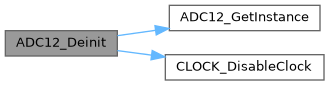
◆ ADC12_Deinit()
| void ADC12_Deinit | ( | ADC_Type * | base | ) |
De-initialize the ADC12 module.
- Parameters
-
base ADC12 peripheral base address.
brief De-initialize the ADC12 module.
param base ADC12 peripheral base address.
Definition at line 174 of file fsl_adc12.c.
Referenced by adc_lld_stop().
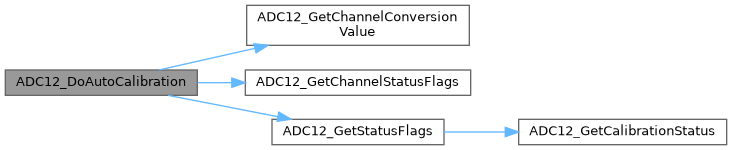
◆ ADC12_DoAutoCalibration()
| status_t ADC12_DoAutoCalibration | ( | ADC_Type * | base | ) |
Automate the hardware calibration.
This auto calibration helps to adjust the gain automatically according to the converter's working environment. Execute the calibration before conversion. Note that the software trigger should be used during calibration.
- Note
- The calibration function has bug in the SOC. The calibration failed flag may be set after calibration process even if you configure the ADC12 as the reference manual correctly. It is a known issue now and may be fixed in the future.
- Parameters
-
base ADC12 peripheral base address.
- Return values
-
kStatus_Success Calibration is done successfully. kStatus_Fail Calibration is failed.
brief Automate the hardware calibration.
This auto calibration helps to adjust the gain automatically according to the converter's working environment. Execute the calibration before conversion. Note that the software trigger should be used during calibration.
note The calibration function has bug in the SOC. The calibration failed flag may be set after calibration process even if you configure the ADC12 as the reference manual correctly. It is a known issue now and may be fixed in the future.
param base ADC12 peripheral base address. retval kStatus_Success Calibration is done successfully. retval kStatus_Fail Calibration is failed.
Definition at line 292 of file fsl_adc12.c.
Referenced by calibrate().

◆ ADC12_EnableDMA()
|
inlinestatic |
Enable generating the DMA trigger when conversion is completed.
- Parameters
-
base ADC12 peripheral base address. enable Switcher of DMA feature. "true" means to enable, "false" means to disable.
Definition at line 303 of file fsl_adc12.h.
◆ ADC12_EnableHardwareTrigger()
|
inlinestatic |
Enable of disable the hardware trigger mode.
- Parameters
-
base ADC12 peripheral base address. enable Switcher of hardware trigger feature. "true" means to enable, "false" means not.
Definition at line 322 of file fsl_adc12.h.
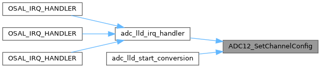
Referenced by adc_lld_start_conversion().

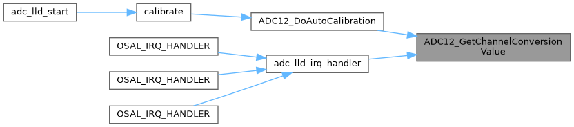
◆ ADC12_GetChannelConversionValue()
|
inlinestatic |
Get the conversion value.
- Parameters
-
base ADC12 peripheral base address. channelGroup Channel group index.
- Returns
- Conversion value.
Definition at line 228 of file fsl_adc12.h.
Referenced by ADC12_DoAutoCalibration(), and adc_lld_irq_handler().
◆ ADC12_GetChannelStatusFlags()
| uint32_t ADC12_GetChannelStatusFlags | ( | ADC_Type * | base, |
| uint32_t | channelGroup | ||
| ) |
Get the status flags of channel.
- Parameters
-
base ADC12 peripheral base address. channelGroup Channel group index.
- Returns
- Flags' mask if indicated flags are asserted. See to "_adc12_channel_status_flags".
brief Get the status flags of channel.
param base ADC12 peripheral base address. param channelGroup Channel group index.
return Flags' mask if indicated flags are asserted. See to "_adc12_channel_status_flags".
Definition at line 262 of file fsl_adc12.c.
Referenced by ADC12_DoAutoCalibration().

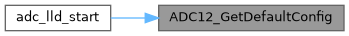
◆ ADC12_GetDefaultConfig()
| void ADC12_GetDefaultConfig | ( | adc12_config_t * | config | ) |
Gets an available pre-defined settings for converter's configuration.
This function initializes the converter configuration structure with an available settings. The default values are:
Example:
- Parameters
-
config Pointer to "adc12_config_t" structure.
brief Gets an available pre-defined settings for converter's configuration.
This function initializes the converter configuration structure with an available settings. The default values are:
Example: code config->referenceVoltageSource = kADC12_ReferenceVoltageSourceVref; config->clockSource = kADC12_ClockSourceAlt0; config->clockDivider = kADC12_ClockDivider1; config->resolution = kADC12_Resolution8Bit; config->sampleClockCount = 12U; config->enableContinuousConversion = false; endcode param config Pointer to "adc12_config_t" structure.
Definition at line 198 of file fsl_adc12.c.
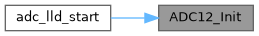
Referenced by adc_lld_start().
◆ ADC12_GetStatusFlags()
| uint32_t ADC12_GetStatusFlags | ( | ADC_Type * | base | ) |
Get the status flags of the converter.
- Parameters
-
base ADC12 peripheral base address.
- Returns
- Flags' mask if indicated flags are asserted. See to "_adc12_status_flags".
brief Get the status flags of the converter.
param base ADC12 peripheral base address.
return Flags' mask if indicated flags are asserted. See to "_adc12_status_flags".
Definition at line 445 of file fsl_adc12.c.
Referenced by ADC12_DoAutoCalibration().


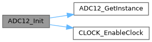
◆ ADC12_Init()
| void ADC12_Init | ( | ADC_Type * | base, |
| const adc12_config_t * | config | ||
| ) |
Initialize the ADC12 module.
- Parameters
-
base ADC12 peripheral base address. config Pointer to "adc12_config_t" structure.
brief Initialize the ADC12 module.
param base ADC12 peripheral base address. param config Pointer to "adc12_config_t" structure.
Definition at line 133 of file fsl_adc12.c.
Referenced by adc_lld_start().
◆ ADC12_SetChannelConfig()
| void ADC12_SetChannelConfig | ( | ADC_Type * | base, |
| uint32_t | channelGroup, | ||
| const adc12_channel_config_t * | config | ||
| ) |
Configure the conversion channel.
This operation triggers the conversion in software trigger mode. In hardware trigger mode, this API configures the channel while the external trigger source helps to trigger the conversion.
Note that the "Channel Group" has a detailed description. To allow sequential conversions of the ADC to be triggered by internal peripherals, the ADC can have more than one group of status and control register, one for each conversion. The channel group parameter indicates which group of registers are used, channel group 0 is for Group A registers and channel group 1 is for Group B registers. The channel groups are used in a "ping-pong" approach to control the ADC operation. At any time, only one of the channel groups is actively controlling ADC conversions. Channel group 0 is used for both software and hardware trigger modes of operation. Channel groups 1 and greater indicate potentially multiple channel group registers for use only in hardware trigger mode. See the chip configuration information in the MCU reference manual about the number of SC1n registers (channel groups) specific to this device. None of the channel groups 1 or greater are used for software trigger operation and therefore writes to these channel groups do not initiate a new conversion. Updating channel group 0 while a different channel group is actively controlling a conversion is allowed and vice versa. Writing any of the channel group registers while that specific channel group is actively controlling a conversion aborts the current conversion.
- Parameters
-
base ADC12 peripheral base address. channelGroup Channel group index. config Pointer to "adc12_channel_config_t" structure.
brief Configure the conversion channel.
This operation triggers the conversion in software trigger mode. In hardware trigger mode, this API configures the channel while the external trigger source helps to trigger the conversion.
Note that the "Channel Group" has a detailed description. To allow sequential conversions of the ADC to be triggered by internal peripherals, the ADC can have more than one group of status and control register, one for each conversion. The channel group parameter indicates which group of registers are used, channel group 0 is for Group A registers and channel group 1 is for Group B registers. The channel groups are used in a "ping-pong" approach to control the ADC operation. At any time, only one of the channel groups is actively controlling ADC conversions. Channel group 0 is used for both software and hardware trigger modes of operation. Channel groups 1 and greater indicate potentially multiple channel group registers for use only in hardware trigger mode. See the chip configuration information in the MCU reference manual about the number of SC1n registers (channel groups) specific to this device. None of the channel groups 1 or greater are used for software trigger operation and therefore writes to these channel groups do not initiate a new conversion. Updating channel group 0 while a different channel group is actively controlling a conversion is allowed and vice versa. Writing any of the channel group registers while that specific channel group is actively controlling a conversion aborts the current conversion.
param base ADC12 peripheral base address. param channelGroup Channel group index. param config Pointer to "adc12_channel_config_t" structure.
Definition at line 237 of file fsl_adc12.c.
Referenced by adc_lld_irq_handler(), and adc_lld_start_conversion().
◆ ADC12_SetGainValue()
|
inlinestatic |
Set the gain value for the conversion result.
This gain value takes effect on the conversion result. If the gain value is not zero, the conversion result is amplified as it.
- Parameters
-
base ADC12 peripheral base address. value Gain value.
Definition at line 291 of file fsl_adc12.h.
◆ ADC12_SetHardwareAverage()
| void ADC12_SetHardwareAverage | ( | ADC_Type * | base, |
| adc12_hardware_average_mode_t | mode | ||
| ) |
Set the hardware average mode.
Hardware average mode provides a way to process the conversion result automatically by hardware. The multiple conversion results are accumulated and averaged internally. This aids to get more accurate conversion result.
- Parameters
-
base ADC12 peripheral base address. mode Setting hardware average mode. See to "adc12_hardware_average_mode_t".
brief Set the hardware average mode.
Hardware average mode provides a way to process the conversion result automatically by hardware. The multiple conversion results are accumulated and averaged internally. This aids to get more accurate conversion result.
param base ADC12 peripheral base address. param mode Setting hardware average mode. See to "adc12_hardware_average_mode_t".
Definition at line 416 of file fsl_adc12.c.
◆ ADC12_SetHardwareCompareConfig()
| void ADC12_SetHardwareCompareConfig | ( | ADC_Type * | base, |
| const adc12_hardware_compare_config_t * | config | ||
| ) |
Configure the hardware compare mode.
The hardware compare mode provides a way to process the conversion result automatically by hardware. Only the result in compare range is available. To compare the range, see "adc12_hardware_compare_mode_t", or the reference manual document for more detailed information.
- Parameters
-
base ADC12 peripheral base address. config Pointer to "adc12_hardware_compare_config_t" structure. Pass "NULL" to disable the feature.
brief Configure the hardware compare mode.
The hardware compare mode provides a way to process the conversion result automatically by hardware. Only the result in compare range is available. To compare the range, see "adc12_hardware_compare_mode_t", or the reference manual document for more detailed information.
param base ADC12 peripheral base address. param config Pointer to "adc12_hardware_compare_config_t" structure. Pass "NULL" to disable the feature.
Definition at line 369 of file fsl_adc12.c.
◆ ADC12_SetOffsetValue()
|
inlinestatic |
Set the offset value for the conversion result.
This offset value takes effect on the conversion result. If the offset value is not zero, the conversion result is substracted by it.
- Parameters
-
base ADC12 peripheral base address. value Offset value.
Definition at line 277 of file fsl_adc12.h.
Variable Documentation
◆ channelNumber
| uint32_t _adc12_channel_config::channelNumber |
Setting the conversion channel number. The available range is 0-31. See channel connection information for each chip in Reference Manual document.
Definition at line 137 of file fsl_adc12.h.
◆ clockDivider
| adc12_clock_divider_t _adc12_config::clockDivider |
Select the divider of input clock source.
Definition at line 115 of file fsl_adc12.h.
◆ clockSource
| adc12_clock_source_t _adc12_config::clockSource |
Select the input clock source to converter.
Definition at line 114 of file fsl_adc12.h.
◆ enableContinuousConversion
| bool _adc12_config::enableContinuousConversion |
Enable continuous conversion mode.
Definition at line 119 of file fsl_adc12.h.
◆ enableInterruptOnConversionCompleted
| bool _adc12_channel_config::enableInterruptOnConversionCompleted |
Generate a interrupt request once the conversion is completed.
Definition at line 140 of file fsl_adc12.h.
◆ hardwareCompareMode
| adc12_hardware_compare_mode_t _adc12_hardware_compare_config::hardwareCompareMode |
Select the hardware compare mode.
Definition at line 127 of file fsl_adc12.h.
◆ referenceVoltageSource
| adc12_reference_voltage_source_t _adc12_config::referenceVoltageSource |
Select the reference voltage source.
Definition at line 113 of file fsl_adc12.h.
◆ resolution
| adc12_resolution_t _adc12_config::resolution |
Select the sample resolution mode.
Definition at line 116 of file fsl_adc12.h.
◆ sampleClockCount
| uint32_t _adc12_config::sampleClockCount |
Select the sample clock count. Add its value may improve the stability of the conversion result.
Definition at line 117 of file fsl_adc12.h.
◆ value1
| int16_t _adc12_hardware_compare_config::value1 |
Setting value1 for hardware compare mode.
Definition at line 128 of file fsl_adc12.h.
◆ value2
| int16_t _adc12_hardware_compare_config::value2 |
Setting value2 for hardware compare mode.
Definition at line 129 of file fsl_adc12.h.