Detailed Description
set engine_type 49 FRANKENSO_QA_ENGINE See also DEFAULT_ENGINE_TYPE Frankenso QA 12 cylinder engine
- Date
- Jan 18, 2015
Definition in file custom_engine.cpp.
Functions | |
| void | setDiscoveryPdm () |
| void | setDiscovery33810Test () |
| void | setFrankensoConfiguration () |
| void | setEtbTestConfiguration () |
| void | setEepromTestConfiguration () |
| void | setL9779TestConfiguration () |
| void | proteusDcWastegateTest () |
| static void | setBasicNotECUmode () |
| void | setBodyControlUnit () |
| void | mreSecondaryCan () |
| void | mreBCM () |
| void | setBoschHDEV_5_injectors () |
| void | setRotary () |
| void | setTest33816EngineConfiguration () |
| void | proteusLuaDemo () |
| void | detectBoardType () |
| void | fuelBenchMode () |
| void | proteusStimQc () |
| void | testEngine6451 () |
Variables | |
| static uint8_t | write_buf [EE_PAGE_SIZE+10] |
| static const I2CEepromFileConfig | i2cee |
| EepromDevice | eepdev_24xx |
| static I2CEepromFileStream | ifile |
Function Documentation
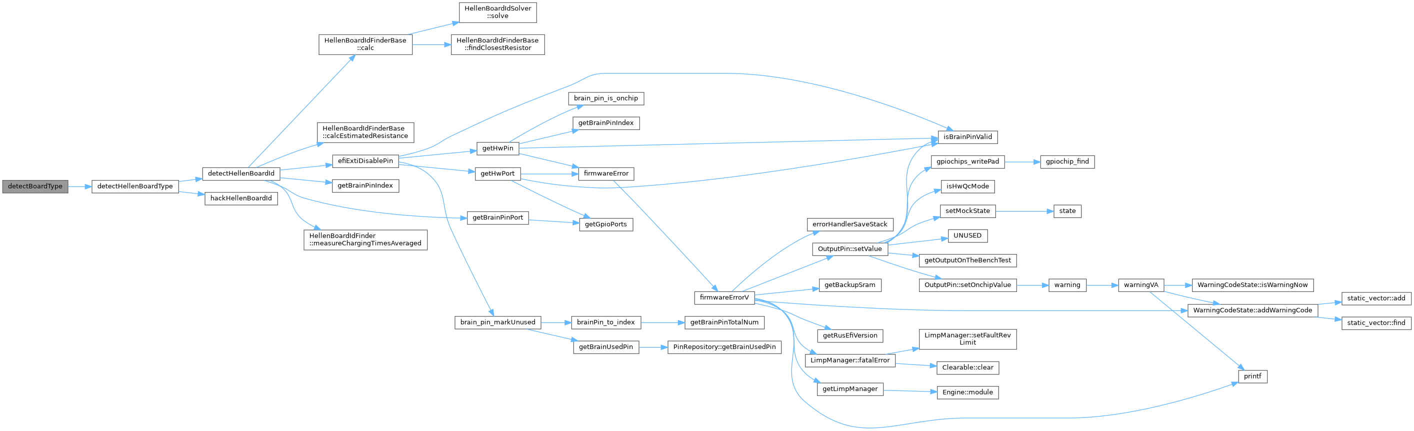
◆ detectBoardType()
| void detectBoardType | ( | ) |
Definition at line 612 of file custom_engine.cpp.
Referenced by runRusEfi().

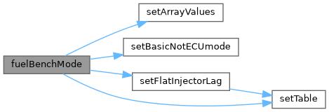
◆ fuelBenchMode()
| void fuelBenchMode | ( | ) |
Definition at line 621 of file custom_engine.cpp.
Referenced by applyEngineType().

◆ mreBCM()
| void mreBCM | ( | ) |
Definition at line 381 of file custom_engine.cpp.
Referenced by applyEngineType().


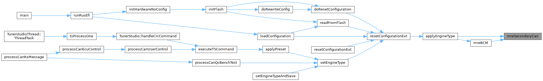
◆ mreSecondaryCan()
| void mreSecondaryCan | ( | ) |
Definition at line 344 of file custom_engine.cpp.
Referenced by applyEngineType(), and mreBCM().

◆ proteusDcWastegateTest()
| void proteusDcWastegateTest | ( | ) |
Definition at line 286 of file custom_engine.cpp.
Referenced by applyEngineType().


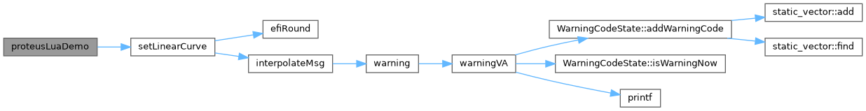
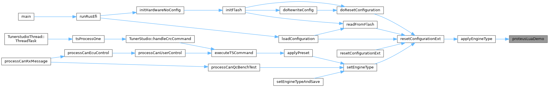
◆ proteusLuaDemo()
| void proteusLuaDemo | ( | ) |
for this demo I use ETB just a sample object to control with PID. No reasonable person should consider actually using Lua for actual intake ETB control while driving around the racing track - hard-coded ETB control is way smarter!
controlIndex = 0 directionIndex = 1
print('pid output ' .. output) print('')
local duty = (bias + output) / 100
– isPositive = duty > 0; – pwmValue = isPositive and duty or -duty – setPwmDuty(controlIndex, pwmValue)
– dirValue = isPositive and 1 or 0; – setPwmDuty(directionIndex, dirValue)
– print('pwm ' .. pwmValue .. ' dir ' .. dirValue)
Definition at line 489 of file custom_engine.cpp.
Referenced by applyEngineType().
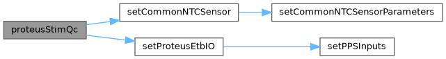
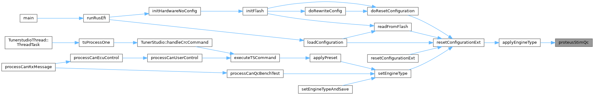
◆ proteusStimQc()
| void proteusStimQc | ( | ) |
Definition at line 635 of file custom_engine.cpp.
Referenced by applyEngineType().
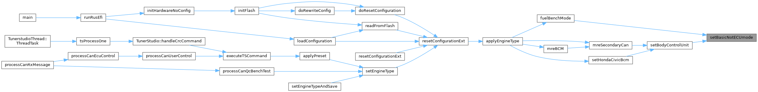
◆ setBasicNotECUmode()
|
static |
Definition at line 315 of file custom_engine.cpp.
Referenced by fuelBenchMode(), and setBodyControlUnit().
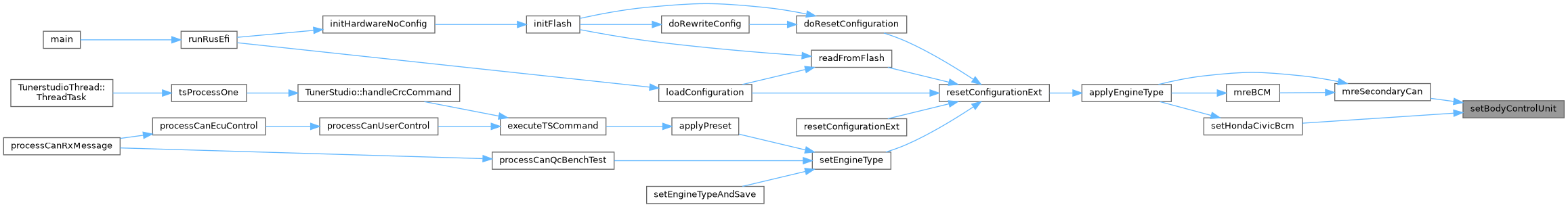
◆ setBodyControlUnit()
| void setBodyControlUnit | ( | ) |
Definition at line 336 of file custom_engine.cpp.
Referenced by mreSecondaryCan(), and setHondaCivicBcm().

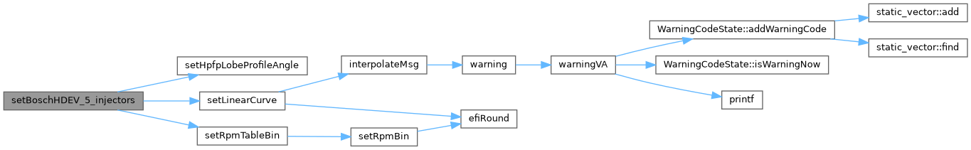
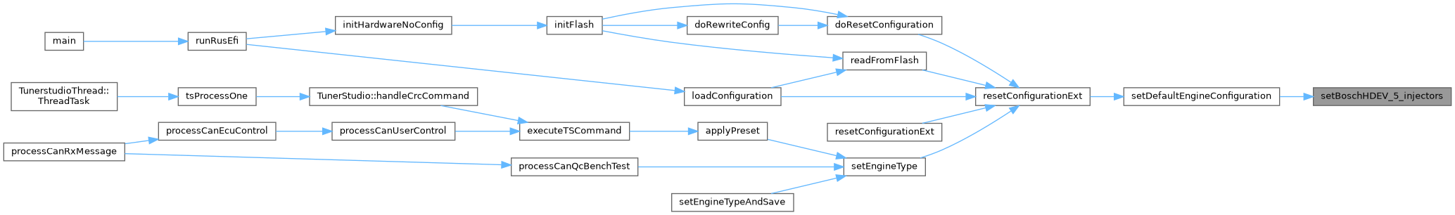
◆ setBoschHDEV_5_injectors()
| void setBoschHDEV_5_injectors | ( | ) |
Definition at line 387 of file custom_engine.cpp.
Referenced by setDefaultEngineConfiguration().
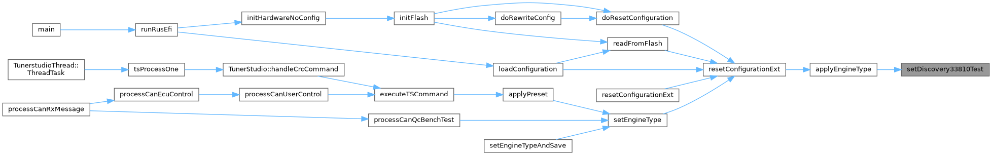
◆ setDiscovery33810Test()
| void setDiscovery33810Test | ( | ) |
set engine_type 59
Definition at line 43 of file custom_engine.cpp.
Referenced by applyEngineType().
◆ setDiscoveryPdm()
| void setDiscoveryPdm | ( | ) |
Definition at line 35 of file custom_engine.cpp.
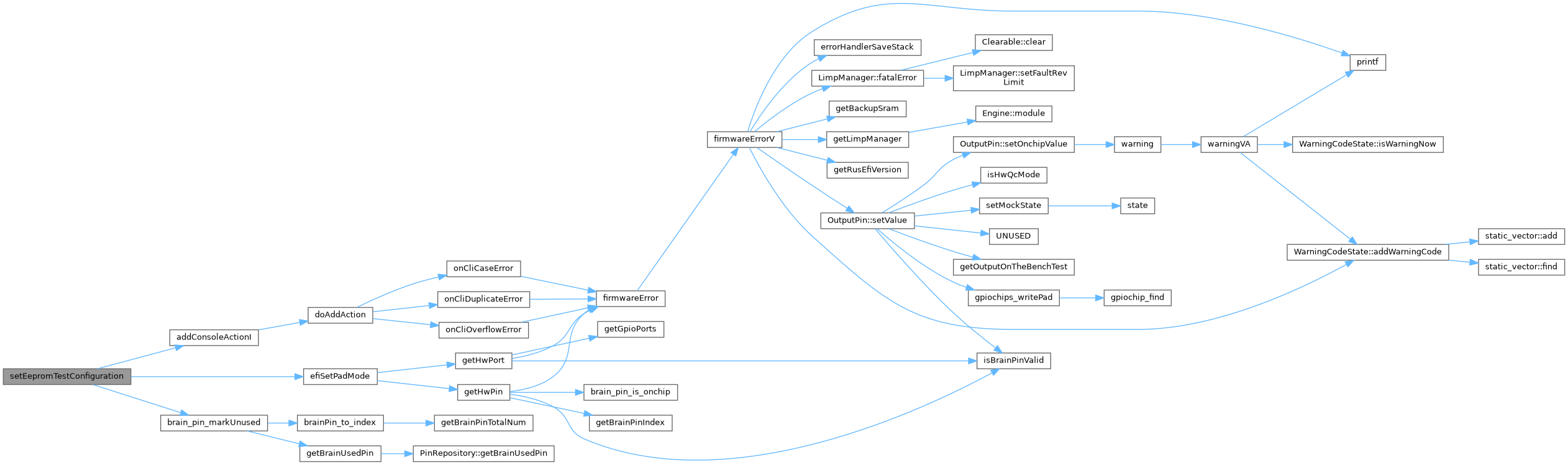
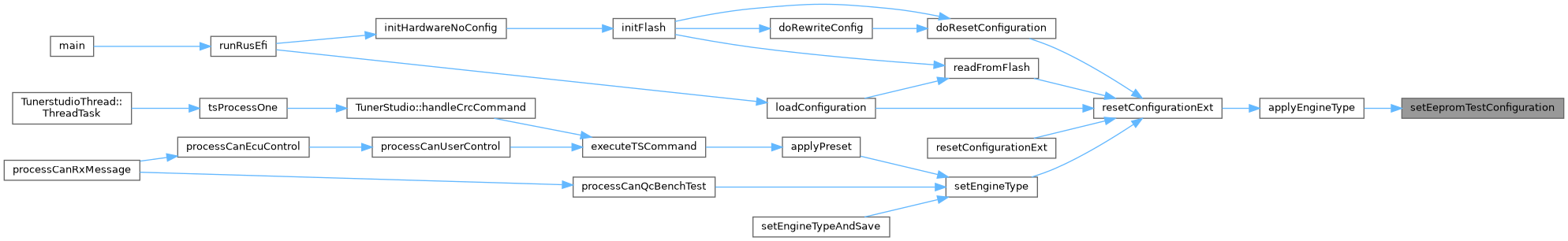
◆ setEepromTestConfiguration()
| void setEepromTestConfiguration | ( | ) |
set engine_type 61
Definition at line 234 of file custom_engine.cpp.
Referenced by applyEngineType().
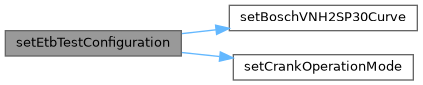
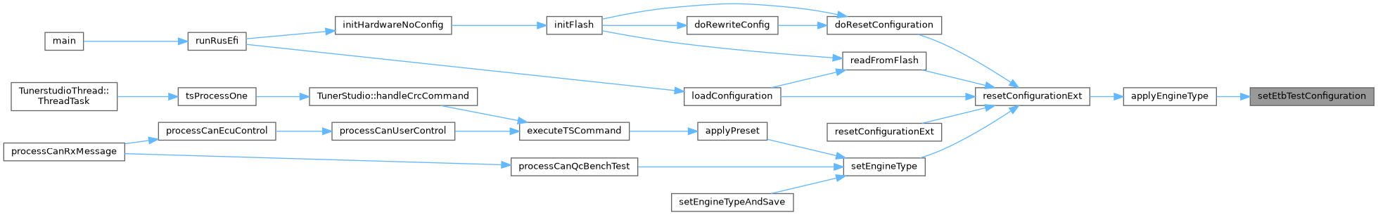
◆ setEtbTestConfiguration()
| void setEtbTestConfiguration | ( | ) |
remember that some H-bridges require 5v control lines, not just 3v logic outputs we have on stm32
Definition at line 160 of file custom_engine.cpp.
Referenced by applyEngineType().
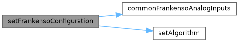
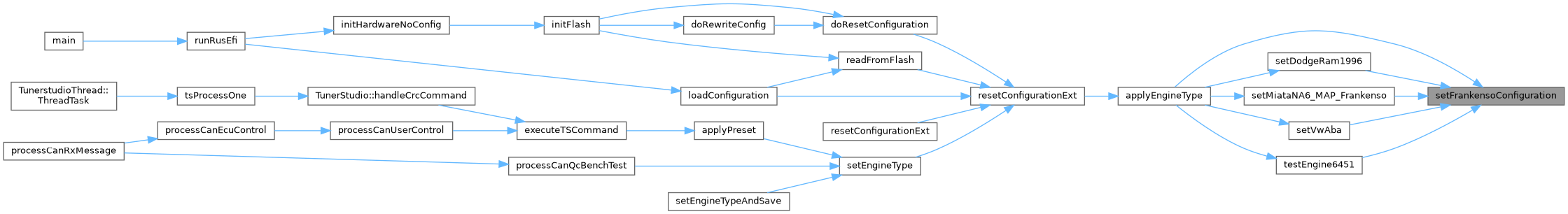
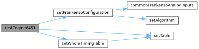
◆ setFrankensoConfiguration()
| void setFrankensoConfiguration | ( | ) |
Frankenso analog #1 PC2 ADC12 CLT Frankenso analog #2 PC1 ADC11 IAT Frankenso analog #3 PA0 ADC0 MAP Frankenso analog #4 PC3 ADC13 WBO / O2 Frankenso analog #5 PA2 ADC2 TPS Frankenso analog #6 PA1 ADC1 Frankenso analog #7 PA4 ADC4 Frankenso analog #8 PA3 ADC3 Frankenso analog #9 PA7 ADC7 Frankenso analog #10 PA6 ADC6 Frankenso analog #11 PC5 ADC15 Frankenso analog #12 PC4 ADC14 VBatt
http://rusefi.com/wiki/index.php?title=Manual:Hardware_Frankenso_board
Definition at line 73 of file custom_engine.cpp.
Referenced by applyEngineType(), setDodgeRam1996(), setMiataNA6_MAP_Frankenso(), setVwAba(), and testEngine6451().
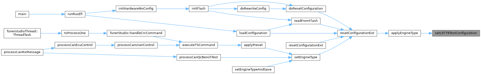
◆ setL9779TestConfiguration()
| void setL9779TestConfiguration | ( | ) |
Definition at line 265 of file custom_engine.cpp.
Referenced by applyEngineType().
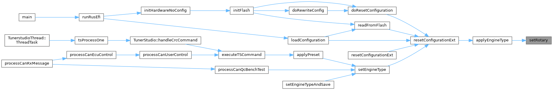
◆ setRotary()
| void setRotary | ( | ) |
set engine_type 107
Definition at line 425 of file custom_engine.cpp.
Referenced by applyEngineType().
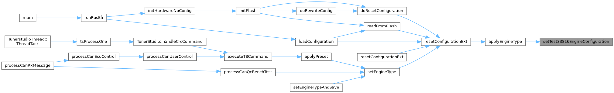
◆ setTest33816EngineConfiguration()
| void setTest33816EngineConfiguration | ( | ) |
set engine_type 103
Definition at line 448 of file custom_engine.cpp.
Referenced by applyEngineType().
◆ testEngine6451()
| void testEngine6451 | ( | ) |
Definition at line 674 of file custom_engine.cpp.
Referenced by applyEngineType().

Variable Documentation
◆ eepdev_24xx
|
extern |
Referenced by setEepromTestConfiguration().
◆ i2cee
|
static |
https://www.onsemi.com/pdf/datasheet/cat24c32-d.pdf CAT24C32
Definition at line 217 of file custom_engine.cpp.
◆ ifile
|
static |
Definition at line 229 of file custom_engine.cpp.
Referenced by setEepromTestConfiguration().
◆ write_buf
|
static |
Definition at line 208 of file custom_engine.cpp.